FordParts
My Garage
My Account
Cart
OEM Ford Edge Coil Springs
Strut Spring- Select Vehicle by Model
- Select Vehicle by VIN
Select Vehicle by Model
orMake
Model
Year
Select Vehicle by VIN
For the most accurate results, select vehicle by your VIN (Vehicle Identification Number).
48 Coil Springs found


Ford Edge Coil Spring, Front Part Number: F2GZ-5310-A
$102.71 MSRP: $149.50You Save: $46.79 (32%)Ships in 1-3 Business Days

Ford Edge Coil Spring, Front Part Number: BT4Z-5310-F
$123.66 MSRP: $180.00You Save: $56.34 (32%)Ships in 1-3 Business Days
Ford Edge Coil Spring, Front Part Number: BT4Z-5310-E
$123.66 MSRP: $180.00You Save: $56.34 (32%)Ships in 1-3 Business Days

Ford Edge Coil Spring, Rear Part Number: BT4Z-5560-N
$111.82 MSRP: $154.70You Save: $42.88 (28%)Ships in 1-2 Business Days
Ford Edge Coil Spring, Rear Part Number: F2GZ-5560-B
$133.92 MSRP: $206.67You Save: $72.75 (36%)Ships in 1-3 Business DaysFord Edge Spring - Rear Part Number: L2GZ-5560-D
$140.40 MSRP: $216.67You Save: $76.27 (36%)Ships in 1-2 Business Days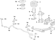
Ford Edge Coil Spring, Front Part Number: K2GZ-5310-C
$81.41 MSRP: $118.50You Save: $37.09 (32%)Ships in 1-3 Business DaysFord Edge Coil Spring, Front Part Number: K2GZ-5310-B
$87.59 MSRP: $127.50You Save: $39.91 (32%)Ships in 1-3 Business DaysFord Edge Coil Spring, Front Part Number: K2GZ-5310-D
$95.49 MSRP: $139.00You Save: $43.51 (32%)Ships in 1-3 Business DaysFord Edge Coil Spring, Front Part Number: F2GZ-5310-B
$103.28 MSRP: $150.33You Save: $47.05 (32%)Ships in 1-3 Business DaysFord Edge Coil Spring, Front Part Number: K2GZ-5310-A
$104.20 MSRP: $151.67You Save: $47.47 (32%)Ships in 1-3 Business DaysFord Edge Coil Spring, Front Part Number: F2GZ-5310-C
$106.71 MSRP: $155.33You Save: $48.62 (32%)Ships in 1-3 Business DaysFord Edge Coil Spring, Front Part Number: F2GZ-5310-E
$107.86 MSRP: $157.00You Save: $49.14 (32%)Ships in 1-3 Business DaysFord Edge Coil Spring, Front Part Number: F2GZ-5310-D
$107.97 MSRP: $157.17You Save: $49.20 (32%)Ships in 1-3 Business DaysFord Edge Coil Spring, Front Part Number: F2GZ-5310-F
$109.92 MSRP: $160.00You Save: $50.08 (32%)Ships in 1-3 Business DaysFord Edge Coil Spring, Front Part Number: K2GZ-5310-L
$113.93 MSRP: $165.83You Save: $51.90 (32%)Ships in 1-3 Business Days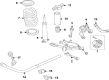
Ford Edge Coil Spring, Rear Part Number: K2GZ-5560-B
$123.66 MSRP: $180.00You Save: $56.34 (32%)Ships in 1-3 Business DaysFord Edge Coil Spring, Front Part Number: K2GZ-5310-E
$125.95 MSRP: $183.33You Save: $57.38 (32%)Ships in 1-3 Business Days

Ford Edge Coil Spring, Front Part Number: 8T4Z-5310-E

Ford Edge Coil Spring, Front Part Number: 7T4Z-5310-A
| Page 1 of 3 |Next >
1-20 of 48 Results
Ford Edge Coil Springs
OEM Coil Springs boasts unmatched quality. Each part goes through full quality checks. They adhere to Ford's official factory standards. These steps remove flaws and inconsistencies. So you can get Coil Springs with long life and a perfect fit. Come to our website and find genuine Ford Edge parts. We keep a wide inventory of OEM Edge parts at the highly affordable prices. It's easy to search, compare, and pick what you need. You'll love the clear info and simple checkout. We offer top-rated customer service, and we reply fast. We also ship promptly to ensure your order arrives on time.
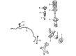
Coil Springs in Ford Edge automobiles are part of the suspenensions sytem that is used to hold the cars developing weight and shock absorbed from the road. They ensure that the car body has the right rise and roll center values which can develop problems such as poor car stability or uneven tire wear. When the coil springs are exhausted there are replacement part they include OEM size and Variable rate or Cargo coils for those who are inclined to transporting heavy loads. There has been the use of linear rate, progressive, as well as dual rate springs in Ford Edge models. Linear rate springs on the other hand provide a rate that does not change and progressive springs provide a changing rate that improves the comfort and the manner in which the car responds to the road. Some types of springs have two different rates: this type of spring is able to manage both comfort and high performance skills. Also, the coil spring that is able to be adjusted so as to control the height or ride can also accept many wheel and tire combinations.
Ford Edge Coil Springs Parts and Q&A
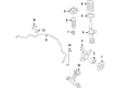
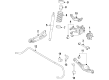
- Q: How to Remove and Replace Rear Suspension Coil Springs in AWD and FWD on Ford Edge?A:The coil spring removal process starts with the wheel and tire removal for rear suspension maintenance of All-Wheel Drive (AWD) and Front Wheel Drive (FWD) vehicles. The Brake Caliper along with its anchor plate should receive mechanic's wire support so the brake hose remains safe during removal of the two anchor plate fastening bolts. You will start by removing the brake disc then disconnecting the stabilizer bar link and parking brake cable bracket from the wheel knuckle before discarding the nut. Carefully move the wheel speed sensor to the side after removing its bolt while also eliminating the two retainers attached to the upper arm when present. Use caution with the brake hose during its removal by both separating the bracket bolt and storing the hose to the side. For AWD vehicles maintain the wheel hub nuts until you utilize the Front Hub Remover to disconnect the halfshaft from the hub and bearing. Using a jackstand for support of the lower arm remove and discard these components: Shock Absorber lower nut and flag bolt, upper arm outboard bolt and nut, toe link outboard bolt and nut, lower arm outboard bolt and nut. AWD-equipped vehicles should store their halfshafts asides through the wheel knuckle opening. Handle the coil spring with extreme caution under high loads and separate it from its positions by pulling on the wheel knuckle while lowering the jackstand before discarding both upper and lower seats. Put a new lower seat correctly into the lower arm while maintaining proper alignment and place the spring onto the lower arm with the spring end positioned between 0 and 10 mm (0-0.39 in) from the step of the spring seat. Proceed with caution when you handle the loaded spring throughout the installation process. The first step involves pulling the wheel knuckle outward before installing the spring while AWD vehicle owners need to place the halfshaft into the wheel bearing and hub assembly. Secure the new lower arm outboard bolt and nut first while keeping nuts loose. After that, install toe link and upper arm bolts and nuts onto the corresponding threads. Begin by putting on the new lower shock nut and flag bolt and then lower the vehicle while removing the jackstand. AWD owners must position the halfshaft into the wheel bearing hub before using the exclusive wheel hub nut to achieve 275 Nm (203 lb-ft) torque. After seating this nut, discard it because the vehicle remains on the ground. Begin by installing new inner wheel hub and outer wheel hub nuts then torquing both components to 275 Nm (203 lb-ft) and 175 Nm (129 lb-ft). Screw and tighten the brake hose bracket bolt to 7 Nm (62 lb-in). Position the wheel speed sensor and screw its bolt to the identical specification before clipping the retainers to the upper arm if your vehicle has them. Connect the parking brake cable bracket with the stabilizer bar link to the wheel knuckle through a 40 Nm (30 lb-ft) torque force. The brake calipers and anchor plate assembly should be put into position before securing it using two anchor plate bolts which need tightening to 55 Nm (41 lb-ft). Apply weight to the wheels before carefully tightening the lower shock nut to 80 Nm (59 lb-ft) and the upper arm outboard bolt and toe link outboard bolt to 175 Nm (129 lb-ft) at the same time. Finish by torquing the lower arm outboard bolt to 80 Nm (59 lb-ft) and turning it an additional 90 degrees. As the last step perform any necessary vehicle alignment checks.
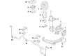
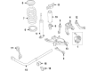
- Q: How to Remove and Replace the Front Coil Springs and Shock Absorber Assembly on Ford Edge?A:You must start the process for removing and replacing front Shock Absorber and spring assembly by removing and discarding four shock absorber upper mount nuts that require new replacement before installation and require tightening to 30 Nm (22 lb-ft). After tire and wheel removal proceed to detach the brake flexible hose bracket bolt from the shock absorber while tightening it to 20 Nm (15 lb-ft) torque when reattaching. Start by separating the shock absorber bracket from the wheel speed sensor harness before removing the shock absorber lower nuts and flag bolts to extract the assembly and discarding those parts. Reverse the removal steps while installing new shock absorber parts by tightening both lower nuts and flag bolts to 225 Nm (166 lb-ft). Alignment procedures should be checked on the front end if necessary. Proper performance with reduced maintenance costs depends on implementing both identical parts with original numbers and equivalent quality elements and complying with torque specifications for assembly component retention.


Related Ford Edge Parts
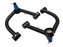 Ford Edge Control Arm
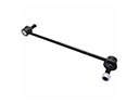 Ford Edge Sway Bar Link
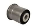 Ford Edge Axle Support Bushings
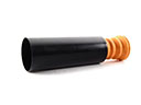 Ford Edge Bump Stop
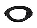 Ford Edge Coil Spring Insulator
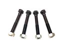 Ford Edge Control Arm Bolt
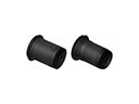 Ford Edge Control Arm Bushing
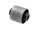 Ford Edge Differential Mount
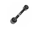 Ford Edge Lateral Link
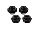 Ford Edge Radius Arm Bushing
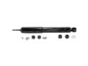 Ford Edge Shock Absorber
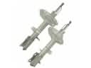 Ford Edge Strut Housing
Browse Ford Edge Coil Springs by Years
2024
2023
2022
2021
2020
2019
2018
2017
2016
2015
2014
2013
2012
2011
2010
2009
2008
2007