FordParts
My Garage
My Account
Cart
Cruise Control System
2001 Ford F-150 Cruise Control Switch
Currently shopping for
2001 Ford F-150
Change VehicleCategories Close X
Currently selected
Electrical
Other Categories
A/C & Heating
Air & Fuel Delivery
Belts & Cooling
Body & Hardware
Brakes
Charging & Starting
Driveline & Axles
Emission Control & Exhaust
Engine
Headlights & Lighting
Interior & Exterior Trim
Maintenance & Lubrication
Steering
Suspension
Transmission
Categories Close X
How to use OE catalog
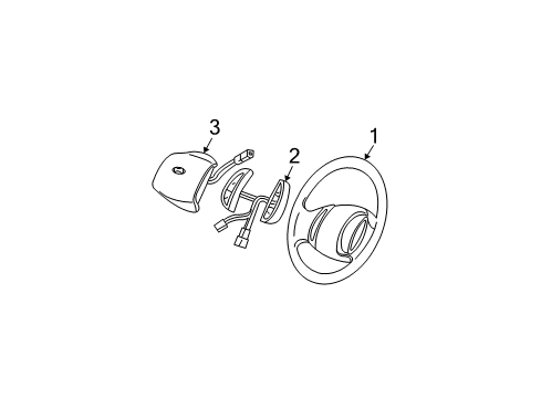
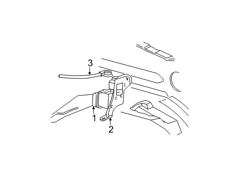
Diagram (1 of 1): Electrical - Cruise Control System
Sort by:
Ref No.
Ref No.
Part No. & Part Description
Price & Qty.
Part No. &
Part Description
Part Description
- 1
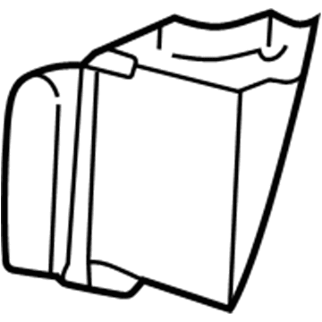 MSRP: $534.80 Your Price: $364.20
- 2
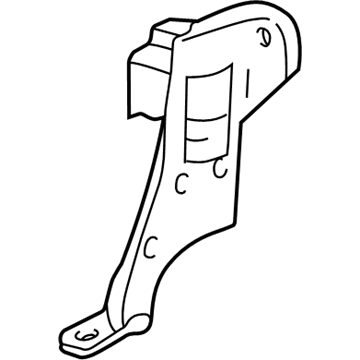
- 3
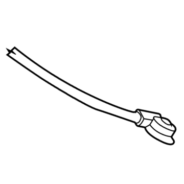
- 3
- 3
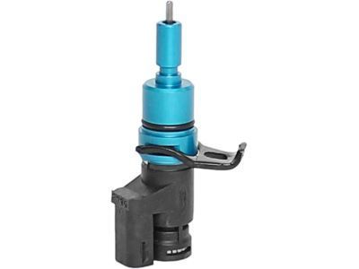
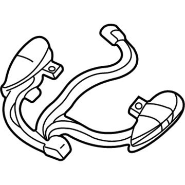
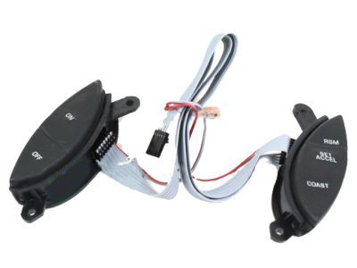
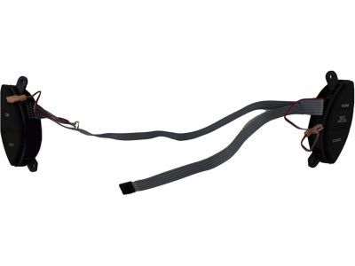
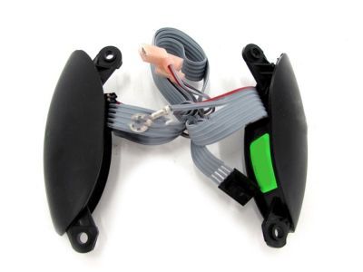
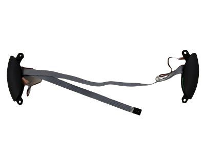 MSRP: $250.91 Your Price: $158.01
- MSRP: $51.19 Your Price: $37.01
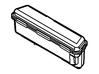
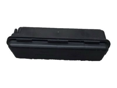
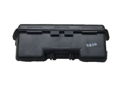 F65Z-9J442-AA
Reservoir Assy- Part Notes: 4 x 4
5.4L SOHC -Supercharge Fuel Injection - Callout Name: 9J442
MSRP: $13.22 Your Price: $9.32
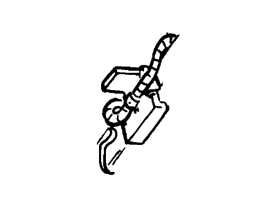
 E9DZ-14A163-AA
Retainer- Part Notes: Retainer - push pin type - 20mm serrated pin with 60mm x 10mm wing - general use for wiring to sheet metal or blind hole retention. Use electrical tape to secure to harness. 10 per package., Service Repair Only
- Callout Name: 14A163
MSRP: $1.58 Your Price: $1.12
 MSRP: $31.65 Your Price: $18.60
 MSRP: $6.75 Your Price: $3.97
 MSRP: $10.00 Your Price: $5.88
 MSRP: $43.40 Your Price: $25.50
 MSRP: $12.50 Your Price: $7.34

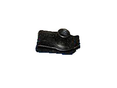 -N623332-S301
Nut - Adjusting Screw- Part Notes: (AM-50-Y)-nut, spring, u-nut, M6x1 - (attaches boot assy to floor pan)
- Require Quantity: 4
- Package Quantity: 4
- Callout Name: 7277
- Replaced By: -W520802-S439
MSRP: $4.00 Your Price: $2.35
OEM 2001 Ford F-150 Parts for Cruise Control System
Genuine OEM 2001 Ford F-150 parts are made using the original design, the high standards, in the Ford official factories, and all of these ensure that they always fit perfectly and easily. FordPartsDeal.com is a trusted source for finding these authentic OEM Cruise Control System parts at very competitive prices. Our professional team is here to help you choose the right 2001 Ford F-150 Cruise Control Switch, and our fast delivery options ensure that your parts are always delivered quickly.
Cruise Control Servo Installation and Repair Tips for 2001 Ford F-150
- Q:How to Remove and Install the Cruise Control Servo and Speed Control Cable Cap on 2001 Ford F-150?A:To take the speed control cable cap off, press the locking tab and turn the cap and then remove the cable between the servo and the cap. Then, loosen the electric connector, loosen the bolts and screws to hold the servo and bracket, leaving the rubber grommets. To install, follow the steps in reverse, the rubber seal must be placed.