FordParts
My Garage
My Account
Cart
OEM 2000 Ford Excursion Intake Manifold
Engine Intake Manifold- Select Vehicle by Model
- Select Vehicle by VIN
Select Vehicle by Model
orMake
Model
Year
Select Vehicle by VIN
For the most accurate results, select vehicle by your VIN (Vehicle Identification Number).
3 Intake Manifolds found


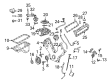
2000 Ford Excursion Intake Manifold Part Number: 2L1Z-9424-AA
$324.61 MSRP: $476.67You Save: $152.06 (32%)Product Specifications- Other Name: Manifold Assembly - Inlet; Engine Intake Manifold; Lower Manifold
- Manufacturer Note: Includes valley stuffer 6P013
- Replaces: YL3Z-9424-CA
- Base No.: 9424
- Item Weight: 29.60 Pounds
- Item Dimensions: 21.7 x 19.6 x 12.6 inches
- Condition: New
- Fitment Type: Direct Replacement
- SKU: 2L1Z-9424-AA
- Warranty: This genuine part is guaranteed by Ford's factory warranty.

2000 Ford Excursion Intake Manifold, Upper Part Number: 9C2Z-9424-A
$2965.50 MSRP: $4393.33You Save: $1427.83 (33%)Product Specifications- Other Name: Manifold Assembly - Inlet; Engine Intake Manifold, Upper; Upper Manifold
- Position: Upper
- Replaces: YC2Z-9424-BA, 2C3Z-9424-AA
- Base No.: 9424A
- Item Weight: 26.50 Pounds
- Item Dimensions: 9.8 x 25.4 x 20.0 inches
- Condition: New
- Fitment Type: Direct Replacement
- SKU: 9C2Z-9424-A
- Warranty: This genuine part is guaranteed by Ford's factory warranty.

2000 Ford Excursion Intake Manifold, Lower Part Number: 4C3Z-9424-AA
$222.46 MSRP: $326.67You Save: $104.21 (32%)Ships in 1-2 Business DaysProduct Specifications- Other Name: Manifold Assembly - Inlet; Engine Intake Manifold, Lower; Lower Manifold
- Manufacturer Note: Lower. Includes 9461 gaskets
- Position: Lower
- Replaces: YC2Z-9424-AA
- Base No.: 9424
- Item Weight: 9.50 Pounds
- Item Dimensions: 8.2 x 22.2 x 10.8 inches
- Condition: New
- Fitment Type: Direct Replacement
- SKU: 4C3Z-9424-AA
- Warranty: This genuine part is guaranteed by Ford's factory warranty.
2000 Ford Excursion Intake Manifold
If you're seeking quality and affordability, look no further than our extensive inventory of genuine 2000 Ford Excursion Intake Manifold available at FordPartsDeal.com. You can confidently purchase our OEM 2000 Ford Excursion Intake Manifold as they are supported by the manufacturer's warranty and our hassle-free return policy, alongside the benefit of our fast delivery service.
2000 Ford Excursion Intake Manifold Parts Q&A
- Q: How to service and repair the intake manifold on 2000 Ford Excursion?A: The first requirement for servicing or repairing the intake manifold is to protect safety through the avoidance of open flames and smoking near fuel parts because volatile mixtures exist. The first task requires the operator to remove the ground battery cable and let the coolant liquid drain from the system. First disconnect and remove the air cleaner outlet tube and use compression on the hose clamp to detach the water outlet hose. Then disconnect the accelerator cable splash shield. First release the fuel system pressure followed by removing the speed control cables together with the accelerator cables after dislodging the return spring. The Bi-fuel vehicle installation requires the removal of compuvalve and vaporizer followed by placing the accelerator cable bracket out of the way. Detach all PCV vacuum and coolant hoses and vacuum lines that attach to the brake booster and engine sensor control wiring harness. Start by removing the right-hand bolt and putting aside the radio interference capacitor while disconnecting the vacuum line alongside the five right-hand fuel injector and five ignition coil electrical connectors. The vehicle requires the removal of the heater hose along with the idle air control motor electrical connector and bypass hose. Often included with the vehicle are the EGR transducer throttle position sensor connectors and EGR transducer vacuum lines which must be disconnected together with the EGR transducer bracket unit. Position the EGR valve to exhaust manifold tube aside before you disconnect the upper fitting and loosen the lower fitting while also disconnecting the EGR valve vacuum line. Start by disconnecting the EVR solenoid electrical and vacuum harness when installed and proceed to eliminate throttle body adapter and gasket. You should remove the EVR bracket when it is present. Disconnect the five electrical connectors of left-hand fuel injectors followed by ignition coil detachments and remove electrical wires connecting the water temperature indicator sender unit. The generator with ignition coils must be removed after separating the ten bolts while disconnecting both the fuel injection supply manifold and its vacuum connector. The bolt removal allows you to move the capacitor aside before disconnecting the cylinder head temperature sensor and extracting the water thermostat along with its housing. The bolts and upper intake manifold need removal along with the disposal of intake manifold gaskets. You can remove the fuel injection supply manifold by unbolted its four bolts first before separating the upper and lower intake manifolds by unbolting ten bolts while avoiding abrasive tools when cleaning mating surface areas of the aluminum retainer plate. To install place the lower intake manifold onto the upper intake manifold then attach the ten bolts loosely before torquing them first to 2 Nm (18 inch lbs.) then to 8-12 Nm (71-106 inch lbs.). Follow this procedure to place the seven bolts on the fuel injector supply manifold and to properly secure the water thermostat housing before tightening the upper intake manifold gasket bolts in two stages at 2 Nm (18 inch lbs.) followed by 20-30 Nm (15-22 ft. lbs.). The cylinder head temperature sensor must be installed while the left-hand radio interference capacitor is positioned along with fuel line and vacuum connection to the fuel injection supply manifold. You must use ten bolts to install the ignition coils before reinstalling the generator along with connecting the water temperature indicator sending unit electrical connector. The left-hand fuel injector electrical connectors and left-hand ignition coil connectors are connected to the system while vehicle manufacturers must install the EVR solenoid bracket by using bolts. The new gasket must be placed between the throttle body adapter before using four bolts to tighten it to 8-10 Nm (71-88 inch lbs.) followed by an additional 85-95 degrees of torque. Then install the EGR valve-to-exhaust manifold tube together with the lower and upper fittings that require tightening to values between 40-60 Nm (30-44 ft. lbs.). Also connect the EVR solenoid vacuum and electrical connectors and the EGR valve vacuum line when these components are available. You should first install the EGR transducer bracket and connect its vacuum lines in addition to the throttle position sensor and EGR transducer electrical connectors. Connect the heater hose alongside the idle air control motor bypass hose and connector in addition to the five right-hand fuel injector electrical connectors and five right-hand ignition coil connectors. You should first link the vacuum lines before placing the right-hand radio interference capacitor in position and subsequently attaching vacuum lines to the brake booster as well as engine control sensor wiring harness. During the installation process the technician should first connect PCV vacuum and coolant hoses and then add the compuvalve with vaporizer for Bi-fuel vehicles. Next, they should position the accelerator bracket followed by bolting it into place. Afterward, they should connect the accelerator and speed control cables with the return spring before adding the accelerator cable splash shield as well as the air cleaner outlet tube. To complete the engine water outlet hose connection install the hose clamp then full the cooling system before reattaching the battery ground cable.
Related 2000 Ford Excursion Parts
 2000 Ford Excursion Fuel Filler Neck
 2000 Ford Excursion Fuel Pump
 2000 Ford Excursion Air Duct
 2000 Ford Excursion Air Filter Box
 2000 Ford Excursion Air Intake Coupling
 2000 Ford Excursion Fuel Pressure Sensor
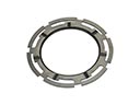 2000 Ford Excursion Fuel Tank Lock Ring
 2000 Ford Excursion Gas Cap
 2000 Ford Excursion Intake Manifold Gasket
 2000 Ford Excursion Mass Air Flow Sensor
 2000 Ford Excursion Throttle Body
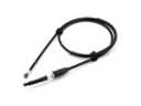 2000 Ford Excursion Throttle Cable