My Garage
Cart
Make sure this part fits

Ford 2L1Z-9424-AA
Intake Manifold

2000-2004 Ford 2L1Z9424AA

Customer Questions & Expert Answers (36)
Ford 2L1Z-9424-AA Intake Manifold
  • Part Description
    Manifold Assembly - Inlet; Engine Intake Manifold
  • Base No.
    9424
  • Replaces
    YL3Z-9424-CA
  • Manufacturer
    Ford
Make sure this part fits
$286.02 MSRP: $420.00
You Save: $133.98 (32%)
1
ADD TO CART
  • Vehicle Fitment

    Year Make Model Trim Engine
    2003 Ford E-150Base8 Cyl 5.4 L GAS
    2003 Ford E-150 Club WagonChateau, XL, XLT8 Cyl 5.4 L GAS
    2000-2002 Ford E-150 EconolineBase, XL8 Cyl 5.4 L GAS
    2000-2002 Ford E-150 Econoline Club WagonChateau, Custom, XL, XLT8 Cyl 5.4 L GAS
    2003 Ford E-250Base8 Cyl 5.4 L CNG, 8 Cyl 5.4 L GAS
    2000-2002 Ford E-250 EconolineBase, XL8 Cyl 5.4 L CNG, 8 Cyl 5.4 L GAS
    2003 Ford E-350 Club WagonChateau, XL, XLT8 Cyl 5.4 L CNG, 8 Cyl 5.4 L GAS
    2000-2002 Ford E-350 Econoline Club WagonChateau, Custom, XL, XLT8 Cyl 5.4 L CNG, 8 Cyl 5.4 L GAS
    2000-2003 Ford E-350 Super DutyBase, XL8 Cyl 5.4 L CNG, 8 Cyl 5.4 L GAS
    2000-2003 Ford ExcursionEddie Bauer, Limited, XLT8 Cyl 5.4 L GAS
    View More
    Warning: California's Proposition 65
  • Customer Questions & Expert Answers

    Q:
    Can you verify if 2L1Z-9424-AA is the right one for my car? Posted by FordPartsDeal Specialist
    A:
    Select Your Vehicle model to verify if part number 2L1Z-9424-AA fits your car.
    Posted by FordPartsDeal Specialist
    Q:
    How to service and repair the lower intake manifold on Ford E-250 Econoline? Posted by Customer
    A:
    The first step when servicing or repairing the lower intake manifold requires complete removal of the upper intake manifold together with EGR valve vacuum hose separation and subsequent removal of the EGR valve tubing upper fitting. Detach the radiator upper hose from the lower intake manifold after which disconnect the water bypass hose followed by the heater water hose. You should maintain careful watch over components related to fuel since highly dangerous flammable mixtures exist so disconnect all fuel lines. The following sequence of electrical connector removal needs to be done: two 16-pin connectors, a 42-pin connector, the Delta HE transducer, the synchronizer, the Crankshaft Position Sensor (CKP sensor), the knock sensor, the oil pressure sensor, the A/C compressor clutch, the Heated Oxygen Sensor (HO2S) (LH), two additional 16-pin connectors, the heated oxygen sensor (RH), the vapor management valve, the Throttle Position (TP) sensor and the Intake Manifold Runner Control (IMRC). You must detach both the IMRC electric connectors and the fuel regulator vacuum line. The IMRC unit along with fuel charging components will be extracted when the lower intake manifold is detached. Untighten both long and short lower intake manifold bolts before extracting and discarding the intake manifold gasket for the LH and RH sides and both the intake manifold rear end seal along with front end seal. When installing the intake manifold apply a Silicone Gasket and Sealant F7AZ-19554-EA bead or an equivalent material that meets Ford specification WSE-M4G323-A4 onto the rear and front ends seal mounting points. Install the seals together with the intake manifold gaskets. The installation procedure demands the lower intake manifold to go into position during the first fifteen minutes post-sealant application while the mechanic must apply sealant to the mounting points. The long and short bolts need two-step tightening from 5 Nm (44 inch lbs.) to 8 - 11.5 Nm (71- 101 inch lbs.). First reconnect the water bypass hose with its clamp. Then connect the fuel lines followed by the fuel pressure regulator vacuum line and the IMRC electrical connector. You should first install the upper radiator hose onto the lower intake manifold then attach the EGR valve vacuum hose and finish by putting on the EGR valve tube upper fitting. The water bypass hose and heater water hose need reconnection in addition to electrical harness connection before installing the upper intake manifold.
    Posted by FordPartsDeal Specialist
    Q:
    How to service and repair the upper intake manifold on Ford E-150? Posted by Customer
    A:
    Starting the upper intake manifold service and repair demands removal of the air cleaner assembly with the engine cover. The first step is to remove the accelerator cable unclips and speed control cable then remove the clip push pin before taking out the accelerator control splash shield by discarding the clip push pin. The installation requires disconnecting the idle air control valve connector before removing the IAC valve assembly. Service of the upper intake manifold begins by disconnecting the throttle body cables of the accelerator control assembly and speed control actuator assembly while disconnecting the cables from their mount on the bracket. Start by removing spark plug wire holders followed by a sequence of taking out 12 bolts mounting the upper intake manifold. Before putting back the parts verify that you have a new accelerator control splash shield clip push pin available and perform necessary inspections on the upper intake manifold gasket replacing it if needed. Sequently fasten bolts first at 6 Nm (53 inch lbs.) and then complete tightening at 10 Nm (89 inch lbs.).
    Posted by FordPartsDeal Specialist
    Q:
    How to service and repair the upper intake manifold on Ford E-250 Econoline? Posted by Customer
    A:
    The service and repair process for the upper intake manifold begins with removing both air cleaner assembly and engine cover. The first step is to unfasten the accelerator cable followed by the speed control cable provided by the vehicle system. Then separate the clip push pin from the accelerator control splash shield before discarding the clip push pin. First disconnect the Idle Air Control (IAC) valve connector and then take out the IAC valve assembly. The service process at the throttle body requires disconnecting the accelerator cable and speed control actuator cable when provided alongside disconnecting these cables from the cable bracket. Take out the spark plug wire holders before unfastening all 12 bolts securing the upper intake manifold. During reinstallation install a new accelerator control splash shield clip push pin while examining the intake manifold upper gasket for damage and requiring replacement if necessary. Bolt tightening procedure consists of two steps: initiate at 6 Nm (53 inch lbs.) before completing at 10 Nm (89 inch lbs.).
    Posted by FordPartsDeal Specialist
    Q:
    How to service and repair the upper intake manifold on Ford E-150 Econoline? Posted by Customer
    A:
    Service and repair of the upper intake manifold starts by taking out the air cleaner assembly together with the engine cover. Unload the accelerator cable and speed control cable only when necessary before you dispose of the push pin clip to discard. Remove the IAC valve by disconnecting its electrical connector then pulling out the assembly. The throttle body requires cable removal for both accelerator cable and speed control actuator cable while present. The cables should be disconnected from their cable bracket before removing their spark plug wire holders. Proceed by taking out the 12 upper intake manifold securing bolts. The installation requires a new accelerator control splash shield clip push pin and a gasket check of the intake manifold upper surface so it can be replaced when needed. The bolt installation consists of two steps where initial torque should be set to 6 Nm (53 inch lbs.) followed by a final torque of 10 Nm (89 inch lbs.).
    Posted by FordPartsDeal Specialist
    Q:
    How to service the intake manifold and spacer assembly on Ford E-150 Econoline? Posted by Customer
    A:
    Initiate service of the intake manifold with spacer assembly by taking out the upper intake manifold while draining part of the cooling system. Unplug the Throttle Position (TP) sensor and remove the brake booster vacuum hose as well as the Vapor Management Valve (VMV) hose and Positive Crankcase Ventilation (PCV) hose and heater water hoses from the intake manifold. Start by unfastening the retaining nut before repositioning the transmission oil level tube bracket and disconnecting both the intake manifold vacuum connector alongside the EGR solenoid electrical and vacuum connectors. The eight bolts holding the intake manifold spacer assembly need to be removed next. You should check the mounting gaskets of the intake manifold spacer assembly for damage before installing it. Replacements must be done if the gaskets show signs of wear. Position the spacer assembly after which tighten the bolts first at 6 Nm and then at 10 Nm. The EGR solenoid electrical and vacuum connectors join along with the intake manifold vacuum connector and the transmission oil level tube bracket requires reinstallation of its retaining nut. You need to restore the heater water hoses along with PCV hose, VMV hose, brake booster vacuum hose, and TP sensor. Once complete you can put in the upper intake manifold and carry out the necessary cooling system fill.
    Posted by FordPartsDeal Specialist
    Q:
    How to service and repair the intake manifold on Ford Excursion? Posted by Customer
    A:
    The first step in repairing or servicing an intake manifold requires users to separate its upper and lower sections before removing bolts while discarding the intake manifold gasket. Both upper and lower manifolds need internal passages and mating surfaces cleaning using a clean metal surface cleaner followed by a complete drying period. Assemble the lower intake manifold gasket with the upper intake manifold on top of the lower intake manifold before inserting the fasteners in a loose state. Use a two-step bolt torquing process to secure the bolts by starting at 2 Nm (18 inch lbs.), followed by 10 Nm (89 inch lbs.) using the documented sequence.
    Posted by FordPartsDeal Specialist
    Q:
    How to service and repair the lower intake manifold on Ford F-150? Posted by Customer
    A:
    The service and repair of the lower intake manifold starts by removing the upper intake manifold and disconnecting both fuel injector electrical connectors and Exhaust Gas Recirculation (EGR) valve vacuum line and EGR valve to exhaust manifold tube upper fitting. The repair of the lower intake manifold begins with upper radiator hose detachment followed by IMRC electrical connector and fuel pressure regulator vacuum line separation and ends when the fuel lines and water bypass hose release their clamp. The removal step includes disassembly of the fuel injection supply manifold and fuel injectors and IMRC component from the lower intake manifold; transfer these parts if you plan to replace this manifold structure. You should discard lower intake manifold sealing components after removing their bolts. To perform the installation, apply Silicone Gasket and Sealant F7AZ-19554-EA which meets Ford specification WSE-M4G323-A4 at front and rear end seal mounting points on the intake manifold before installing front and rear end seals and intake manifold gaskets. Place the lower intake manifold after no longer than four minutes from applying sealant then position it and apply sealant to the mounting points. The six long bolts and eight short bolts need to be tightened in a two-step process starting at 5 Nm (44 inch lbs.) and concluding at 10 Nm (89 inch lbs.). procedure includes reattaching both the water bypass hose with clamp and fuel lines if required alongside connecting the fuel pressure regulator vacuum line and IMRC electrical connector. Conclude the process by attaching the upper radiator hose while connecting the EGR valve vacuum hose and placing the EGR valve to exhaust manifold tube upper fitting. Complete the task by attaching the fuel injector electrical connectors before reinstalling the upper intake manifold.
    Posted by FordPartsDeal Specialist
    Q:
    How to service and repair the intake manifold on a 4.6L engine on Ford F-150 Heritage? Posted by Customer
    A:
    A proper approach to service and repair the intake manifold of a 4.6L engine starts with disconnecting the battery ground cable while removing the air cleaner outlet pipe. The first step is to drain the engine cooling system followed by clamping and sliding the hose clamp to take away the upper radiator hose. The service requires removing three components from the throttle body cam by disconnecting the accelerator cable and speed control actuator cable and removing the accelerator return spring. First disconnect the bolts on the accelerator cable bracket then place all these elements aside. The procedure requires removal of the main vacuum harness together with the Idle Air Control (IAC) fresh air hose, differential pressure feedback Exhaust Gas Recirculation (EGR) sensor electrical connector, and EGR vacuum regulator solenoid connections. The service technician should separate the electrical connections of IAC and TP sensor while also detaching the EGR valve vacuum hose, the EVAP canister purge valve hose and its associated vacuum lines from the fuel pressure regulator and EVAP canister purge valve. Drain the nut which disconnects the brake booster tube before setting the bracket and tube aside while placing the crankcase ventilation hose to the side. First disconnect the vacuum hoses from the EGR valve tube then position the exhaust manifold to EGR valve tube aside before disconnecting the upper fitting while loosening the lower fitting. Disconnect all spring-lock fuel hose couplings together with heater hose and heated throttle body inlet hose and finally the PCV hose itself. You should disconnect the heated PCV fitting hose followed by removing the throttle body adapter while discarding the gasket and checking throttle body and adapter for potential damage. Initialize this process by removing the four bolts to let you advance the throttle body adapter slightly. Detach the eight ignition coils and the eight fuel injectors after removing the bolts and power steering reservoir upper mounting bracket. To access the engine components the technician should first deviate the belt tensioner clockwise then remove the bolts from the generator upper mount attached to the alternator pulley followed by the lower mount generator bolts which exit from the generator to place it out of the way. Separate the bolts from the thermostat housing but discard both components and the O-ring seal while removing the nine bolts to gain access to the intake manifold assembly which requires lifting for disconnecting its tuning valve electrical connector before disposal of gaskets followed by inspecting for damage. The first step for installation requires a plastic scraper to clean all sealing surfaces before positioning new intake manifold gaskets and the upper intake manifold with loose nine bolts. Install the thermostat with new O-ring seal after connecting the intake manifold tuning valve electrical connector then secure the 11 thermostat housing bolts by first tightening them to 2Nm (18 inch lbs.) and second to 25 Nm (18 ft. lbs.). Place the generator in position then begin attaching lower mounting bolts and proceed to install upper mounting bracket and bolts. Tightly rotate the belt tensioning tool clockwise to put on the accessory drive belt according to the routing directions on the radiator upper air deflector. Attach eight fuel injector electrical connectors to their respective locations before mounting the eight ignition coils. Start by placing the power steering reservoir upper mounting bracket followed by its bolts until tight then move onto position the throttle body adapter followed by attaching the heated PCV fitting hose using a new gasket with throttle body adapter bolts. First prepare the heated PCV fitting hose and heater hose and exhaust manifold-to-EGR valve tube by hand-tightening fittings before final installation of upper and lower fittings. You must connect the fuel hose spring lock couplings then add the brake booster vacuum tube together with its bracket before installing the nut. Attachment of vacuum harness should come first followed by connecting the EVAP canister purge valve vacuum hose then the vacuum hoses going to the EGR valve tube followed by the fuel pressure regulator vacuum hose and the EVAP canister purge valve hose finally and the EGR valve vacuum hose. The next step includes linking the TP sensor and IAC electrical connectors and the EGR vacuum regulator solenoid connections and the IAC fresh air hose and differential pressure feedback EGR sensor electrical connector, then finish with the main vacuum harness connection. The accelerator cable bracket must be installed with bolts after connecting the throttle body cam to all accelerator controls and their respective components such as cable and speed control actuator cable with throttle return spring. The last step requires connection of the upper radiator hose before clamping it down while installing the air cleaner outlet pipe followed by battery ground cable reconnection to complete engine cooling system filling and bleeding.
    Posted by FordPartsDeal Specialist
    Q:
    How to service and repair the upper intake manifold on Lincoln Blackwood? Posted by Customer
    A:
    Service and repair of the upper intake manifold begins with disconnecting the battery negative cable followed by air cleaner assembly removal. First remove the three bolts which fasten the engine appearance cover before disconnecting the accelerator cable together with the speed control cable and return spring. After bolt removal position these parts out of the way. The upper servicing routine requires disconnecting the Evaporative Emission (EVAP) return hose along with the positive crankcase ventilation (PCV) valve tube and then concluding with coolant hoses where all physical connections receive plug installation to avoid coolant escape. You should disconnect the tuning valve electrical connector and then remove the cowl grille followed by taking out the bolts along with five clips and the wiring harness shield. Use a plastic scraping tool to clean all surfaces while carefully discarding old gaskets because metal scrapers along with abrasive tools should be avoided on sealing areas when removing the bolts, stud and balance tube. Disconnect and separate the electrical connectors linking the Idle Air Control motor and Throttle Position sensor and exhaust both the vacuum pressure hoses and EGR vacuum regulator electrical connector. Use a wrench to detach the bolts and the nut from the power steering reservoir bracket before safely placing it away and then remove the stud and oil fill tube. First detach the brake booster vacuum hose followed by the vacuum hose from the EGR valve and then unfasten the bolts on the EGR adapter. You need to disconnect the vacuum hose from the Vapor Management Valve (VMV) before placing it to the side. The upper intake manifold bolts should be removed while noting they are not reusable before extracting the upper intake manifold for gasket evaluation with cleaning applying to each sealing surface. The installation process requires examinations of both upper intake manifold gaskets for usability and notes the use of new upper intake manifold bolts. Begin installation by fitting all parts with their gaskets and upper intake manifold before tightening the bolts in two steps at 10 Nm (89 inch lbs.) followed by an additional 90-degree turn. The service technician needs to reattach the VMV vacuum hose before installing the EGR adapter together with a new gasket which requires bolted installation. The vacuum hose connections should run from the EGR valve to the brake booster while positioning the oil fill tube and reinstalling the power steering reservoir bracket with bolts. Next attach the nut while you join all necessary components between the differential pressure feedback EGR and EGR vacuum regulator and the IAC valve and TP sensor electrical connectors. The technician should install balance tube gaskets along with the balance tube before proceeding to mount the wiring harness shield together with its bolts and clips. Follow this step plan to reinstall the cowl grille and connect the intake manifold tuning valve electrical connector before reattaching the PCV valve tube together with coolant hoses. The repair process ends with connecting the EVAP return hose then reinstalling the cables and bracket before fastening everything with bolts before returning the accelerator cable and speed control cable and return spring. The process finishes with installation of the engine appearance cover together with air cleaner assembly and battery negative cable reconnection followed by filling the engine cooling system.
    Posted by FordPartsDeal Specialist
    Q:
    How to service and repair the lower intake manifold on Lincoln Blackwood? Posted by Customer
    A:
    Operation on the lower intake manifold starts with demolishing the upper intake manifold before cutting off every fuel line connection and disconnecting the engine water bypass hose as well as water temperature indicator sender electrical connector and upper radiator hose and heated water inlet hose and heated positive crankcase ventilation (PCV) hose. The generator upper support bracket requires removal of its four bolts and the fuel injector electrical connectors need detachment before removing the vacuum hose from the pressure regulator to set it aside. Remove the lower intake manifold bolts while discarding both objects and their bolts according to service information. Start by extracting the bolts together with the radio ignition interference capacitors before you evaluate the gaskets and the valley stuffer which will be removed for cleaning the sealing surfaces. First position the valley stuffer then check the condition of reusable lower intake manifold gaskets before replacing them if needed. You should start the new lower intake manifold bolts by hand at positions 7-12 first and then move to positions 1-6 before installing the gaskets and lower intake manifold. Tighten the bolts in two steps by first applying 10 Nm (89 inch lbs.) followed by turning them 90 degrees additional. Install radio ignition interference capacitors and reconnect pin type wiring harness retainers to their respective sockets and the water temperature indicator sensor electrical connector. The installation requires placing the vacuum harness while attaching the vacuum hose to the fuel injector pressure regulator followed by reconnecting all eight fuel injector electrical connectors. The generator upper support bracket requires installation through use of four bolts followed by reintroduction of heated water inlet hose and upper radiator hose and heated PCV hose and engine water bypass return hose and fuel lines before finally installing the upper intake manifold.
    Posted by FordPartsDeal Specialist
    Q:
    How to Address Issues with the Intake Manifold on a Lincoln Navigator? Posted by Customer
    A:
    Step one for lower intake manifold service requires complete upper intake manifold removal. Remove the fuel hose spring lock couplings, engine water bypass hose, water temperature indicator sender electrical connector, upper radiator hose, heater water inlet hose and heated Positive Crankcase Ventilation (PCV) water heated fitting inlet hose. Rephrase the generator upper support bracket's four securing bolts then detach the eight fuel injectors followed by cutting the fuel injector pressure regulator vacuum hose and keeping it aside. After separating the wire harness pin-type retainer people should remove the bolts and lower intake manifold while discarding the bolts. Examine the gaskets first then install new gaskets if they are needed before reconnecting the bolts for radio ignition interference capacitors. Declaration of old sealant requires plastic tools instead of metal scrapers and wire brushes because abrasive devices should be avoided for cleaning sealing surfaces. Use new bolts to loosely attach the lower intake manifold by placing the lower intake gaskets and the radio ignition interference capacitors. Tighten the retaining bolts to 10 Nm (89 inch lbs.) while also torquing them 90 degrees further before you connect the wire harness pin-type retainer and the water temperature indicator sensor electrical connector. Place the vacuum harness while connecting the vacuum line to the fuel injector pressure regulator then proceed with the eight fuel injector electrical connector attachment. After installing the top generator support bracket using four bolts the technician should connect the heater water inlet hose with the upper radiator hose and the water heated fitting inlet hose before topping off with the engine water bypass return hose. The last step involves reinstalling the upper intake manifold after reattaching the fuel hose spring lock couplings.
    Posted by FordPartsDeal Specialist
    Q:
    How to service and repair the lower intake manifold on Lincoln Navigator? Posted by Customer
    A:
    The lower intake manifold service requires starting with upper intake manifold removal. Disconnect the sequence of parts starting with the fuel hose spring lock couplings, engine water bypass hose, water temperature indicator sender electrical connector, upper radiator hose, heater water inlet hose, and heated Positive Crankcase Ventilation (PCV) water heated fitting inlet hose. Remove the four bolts which hold the generator upper support bracket before disconnecting the eight fuel injectors and fuel injector pressure regulator vacuum hose that leads out of the working area. Start by disconnecting the wire harness pin-type retainer before unscrewing the bolts for lower intake manifold removal and then discard the bolts. Check gaskets for the radio ignition interference capacitors while removing their bolts and install new gaskets when needed but avoid using metal scrapers to clean sealing surfaces instead use a plastic scraping tool. Install the lower intake gaskets together with radio ignition interference capacitors through new bolts while mounting the lower intake manifold loosely. The technician should perform a two-step process when tightening the retaining bolts by starting at 10 Nm (89 inch lbs.) then continuing to 90° according to the specified sequence. Reconnect the wire harness pin-type retainer which includes the water temperature indicator sensor electrical connector and the vacuum line to the fuel injector pressure regulator. The eight fuel injector electrical connectors must be installed before reinstalling the upper generator support bracket with its four bolts and connecting the heater water inlet hose with the upper radiator hose and water heated fitting inlet hose. Before placing back the upper intake manifold you must connect both the engine water bypass return hose and the fuel hose spring lock couplings.
    Posted by FordPartsDeal Specialist
    Q:
    How soon must the lower intake manifold be positioned after applying sealant for the 2003 Ford E-250? Posted by Customer
    A:
    The lower intake manifold must be positioned within fifteen minutes of applying sealant, ensuring the correct bolt locations as noted during removal.
    Posted by FordPartsDeal Specialist
    See expert answers on similar Intake Manifold
    Q:
    What is the next step after disconnecting the vacuum line for the 2002 Ford Expedition? Posted by Customer
    A:
    Proceed to remove the bolts and the lower intake manifold, followed by the bolts and the radio ignition interference capacitors.
    Posted by FordPartsDeal Specialist
    See expert answers on similar Intake Manifold
    Q:
    What should be disconnected before starting the repair for the 2001 Ford Excursion? Posted by Customer
    A:
    Disconnect the battery ground cable and drain the coolant system.
    Posted by FordPartsDeal Specialist
    See expert answers on similar Intake Manifold
    Q:
    What is the final step in the installation process for the 2002 Ford Excursion? Posted by Customer
    A:
    Fill the cooling system and finally connect the battery ground cable.
    Posted by FordPartsDeal Specialist
    See expert answers on similar Intake Manifold
    Q:
    What is the time limit for installing the lower intake manifold after applying sealant for the 2002 Ford E-250 Econoline? Posted by Customer
    A:
    The lower intake manifold must be installed within fifteen minutes of applying sealant.
    Posted by FordPartsDeal Specialist
    See expert answers on similar Intake Manifold
    Q:
    What must be done if replacing the lower intake manifold for the 2001 Ford E-250 Econoline? Posted by Customer
    A:
    The IMRC must also be removed.
    Posted by FordPartsDeal Specialist
    See expert answers on similar Intake Manifold
    Q:
    What should be connected after reattaching the EGR valve for the 2001 Ford Expedition? Posted by Customer
    A:
    Connect the idle air control motor, fuel lines, brake booster vacuum line and bracket, differential pressure feedback EGR connections, vapor management valve vacuum line, fuel pressure regulator vacuum line, throttle position sensor connector, engine vacuum regulator connector, and the main vacuum harness.
    Posted by FordPartsDeal Specialist
    See expert answers on similar Intake Manifold
    Q:
    What is the installation procedure for the intake manifold for the 2000 Ford Excursion? Posted by Customer
    A:
    Position the lower intake manifold to the upper intake manifold, loosely install the ten bolts, and tighten them in two stages.
    Posted by FordPartsDeal Specialist
    See expert answers on similar Intake Manifold
    Q:
    What is the final step in the process for the 2004 Ford Expedition? Posted by Customer
    A:
    Reconnect the main vacuum harness, install the accelerator cable bracket and bolts, connect the throttle body cam, accelerator cable, speed control actuator cable, and throttle return spring, then install the appearance cover mounting bracket with three bolts, connect the upper radiator hose and position the clamp, install the air cleaner outlet pipe, reconnect the battery ground cable, and fill and bleed the engine cooling system.
    Posted by FordPartsDeal Specialist
    See expert answers on similar Intake Manifold
    Q:
    What should be done with the accelerator cable bracket for the 2003 Ford Excursion? Posted by Customer
    A:
    Position the accelerator cable bracket aside and remove the bolts.
    Posted by FordPartsDeal Specialist
    See expert answers on similar Intake Manifold
    Q:
    What should be done with the accelerator cable bracket for the 2000 Ford Expedition? Posted by Customer
    A:
    Remove the accelerator cable bracket bolts and set the bracket and cables aside.
    Posted by FordPartsDeal Specialist
    See expert answers on similar Intake Manifold
    Q:
    What is the final step before reconnecting the battery ground cable for the 2003 Ford Expedition? Posted by Customer
    A:
    Install the air cleaner outlet pipe and fill and bleed the engine cooling system.
    Posted by FordPartsDeal Specialist
    See expert answers on similar Intake Manifold
    Q:
    What should be inspected after removing the upper intake manifold for the 2003 Ford F-150? Posted by Customer
    A:
    Inspect the upper gasket and install a new one if necessary.
    Posted by FordPartsDeal Specialist
    See expert answers on similar Intake Manifold
    Q:
    What should be done with the intake manifold upper gasket for the 2000 Ford E-150 Econoline? Posted by Customer
    A:
    Discard the intake manifold upper gasket.
    Posted by FordPartsDeal Specialist
    See expert answers on similar Intake Manifold
    Q:
    How should the intake manifold and thermostat outlet be installed for the 2000 Ford F-150? Posted by Customer
    A:
    Position the manifold and thermostat outlet, then install and tighten the bolts in two stages: first to 2 Nm (18 inch lbs.) and then to 25 Nm (19 ft. lbs.).
    Posted by FordPartsDeal Specialist
    See expert answers on similar Intake Manifold
    Q:
    What are the next steps after removing the fuel rail for the 2001 Ford F-150? Posted by Customer
    A:
    Disconnect the water bypass hose and the heated positive crankcase ventilation (PCV) system heater water hose, then remove the long and short lower intake manifold bolts and take out the lower intake manifold, discarding the sealing components.
    Posted by FordPartsDeal Specialist
    See expert answers on similar Intake Manifold
    Q:
    How do you separate the upper and lower intake manifolds for the 2002 Ford F-250 Super Duty? Posted by Customer
    A:
    If necessary, remove the fuel injection supply manifold by taking out the four bolts, then separate the upper and lower intake manifolds by removing the ten bolts.
    Posted by FordPartsDeal Specialist
    See expert answers on similar Intake Manifold
    Q:
    What is the final step in the installation process for the 2002 Ford F-350 Super Duty? Posted by Customer
    A:
    Connect the engine water outlet hose and position the hose clamp, fill the cooling system, and finally connect the battery ground cable.
    Posted by FordPartsDeal Specialist
    See expert answers on similar Intake Manifold
    Q:
    What should be connected after securing the intake manifold for the 2000 Lincoln Navigator? Posted by Customer
    A:
    Connect the water temperature indicator sensor, reposition the vacuum harness, and connect the vacuum line to the fuel injector pressure regulator.
    Posted by FordPartsDeal Specialist
    See expert answers on similar Intake Manifold
    Q:
    What vacuum lines need to be disconnected for the 2002 Lincoln Navigator? Posted by Customer
    A:
    Disconnect the brake booster vacuum line and other vacuum lines from the EGR valve.
    Posted by FordPartsDeal Specialist
    See expert answers on similar Intake Manifold
    Q:
    What should be done with the power steering reservoir bracket for the 2004 Lincoln Navigator? Posted by Customer
    A:
    Remove the nut and the bolts from the power steering reservoir bracket, positioning it aside.
    Posted by FordPartsDeal Specialist
    See expert answers on similar Intake Manifold
    Q:
    What should be reconnected after securing the upper intake manifold for the 2002 Ford F-150? Posted by Customer
    A:
    Reconnect the spark plug wire holders.
    Posted by FordPartsDeal Specialist
    See expert answers on similar Intake Manifold
    Q:
    How should sealing surfaces be cleaned for the 2003 Lincoln Navigator? Posted by Customer
    A:
    Do not use metal scrapers or abrasive tools; instead, use a plastic scraping tool to remove old sealant and discard the gaskets.
    Posted by FordPartsDeal Specialist
    See expert answers on similar Intake Manifold
    If you have any questions about this product, please don't hesitate to ask us. We will be happy to help you!

OEM Ford Intake Manifold 2L1Z-9424-AA Designed for Proper Fit and Performance

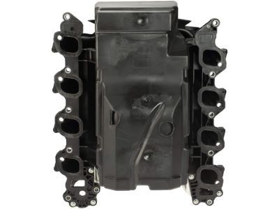
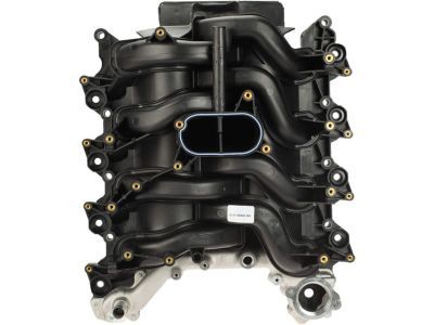
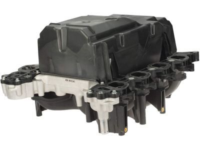
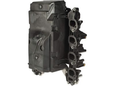
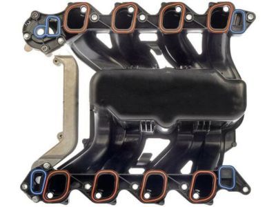
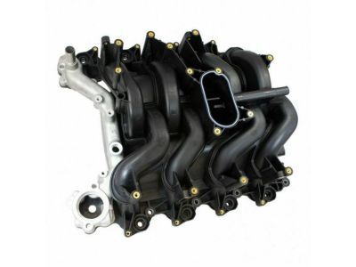
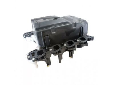
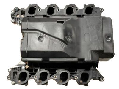
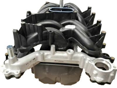
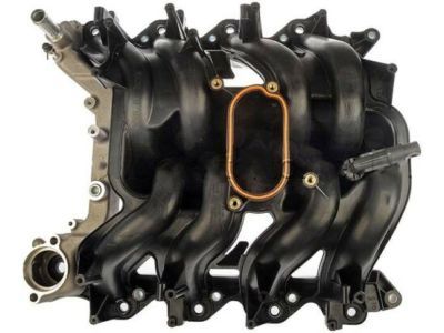
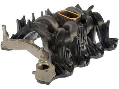
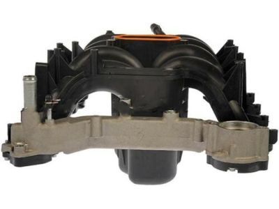
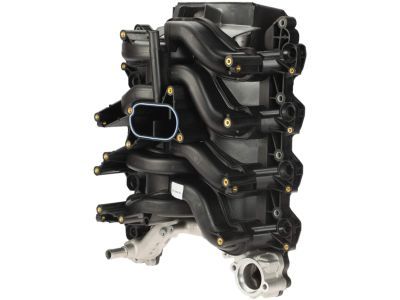
The Ford part 2L1Z-9424-AA Intake Manifold as a genuine Ford Intake Manifold component delivers both authenticity and reliability. This item carries a warranty from the manufacturer which guarantees 12-month, 12,000-mile of use. The Ford 2L1Z-9424-AA Intake Manifold is used with Ford F-150, Excursion, Expedition vehicles and Lincoln Navigator, Blackwood models. The original Ford part will bear the manufacturer part number: 2L1Z-9424-AA and where it is made at Ford. It has the code: 9424.
This component has dimensions of 21.7 x 19.6 x 12.6 inches and its weight is approximately 29.60 Pounds. The part 2L1Z9424AA is available in New condition while meeting the standards of the product rating. The Manifold Assembly - Inlet; Engine Intake Manifold belongs to the Direct Replacement category to guarantee it is suitable for its specific vehicle applications. This part 2L1Z-9424-AA can be known as Lower Manifold, and it replaces YL3Z-9424-CA. The inventory reference for this item is SKU: 2L1Z-9424-AA. Additional manufacturer-provided details include: Includes valley stuffer 6P013. The Ford manufacturer issues a factory warranty for this component which ensures dependable operation and peak performance. You can find delivery and returns information on our Shipping Policy and Return Policy pages.
Original equipment manufacturer parts are of the top standards and their performance is outstanding and top notch. This is explained by the fact that they follow the official manufacturing techniques of Ford, use of premium material and meets high standards of quality. Our site is worth visiting, in case you need high-quality and affordable OEM Ford components. We promise the optimal priced Ford parts on a wide range. You can relax that all OEM products you buy from us include a manufacturer warranty and will be covered by our simple and easy-to-use return policy, so you will not worry about buying a part.