FordParts
My Garage
My Account
Cart
OEM 2000 Ford Mustang Clock Spring
Spiral Cable Clock Spring- Select Vehicle by Model
- Select Vehicle by VIN
Select Vehicle by Model
orMake
Model
Year
Select Vehicle by VIN
For the most accurate results, select vehicle by your VIN (Vehicle Identification Number).
1 Clock Spring found


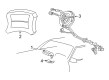
2000 Ford Mustang Clockspring Part Number: 1R3Z-14A664-AA
$118.83 MSRP: $172.97You Save: $54.14 (32%)Ships in 1-3 Business DaysProduct Specifications- Other Name: Cover And Contact Plate Assembly; Air Bag Clockspring
- Replaces: XR3Z-14A664-AA
- Base No.: 14A664
- Item Weight: 4.20 Pounds
- Item Dimensions: 6.0 x 4.5 x 10.5 inches
- Condition: New
- Fitment Type: Direct Replacement
- SKU: 1R3Z-14A664-AA
- Warranty: This genuine part is guaranteed by Ford's factory warranty.
2000 Ford Mustang Clock Spring
If you're seeking quality and affordability, look no further than our extensive inventory of genuine 2000 Ford Mustang Clock Spring available at FordPartsDeal.com. You can confidently purchase our OEM 2000 Ford Mustang Clock Spring as they are supported by the manufacturer's warranty and our hassle-free return policy, alongside the benefit of our fast delivery service.
2000 Ford Mustang Clock Spring Parts Q&A
- Q: What Precautions Should Be Taken When Servicing the Clock Spring on 2000 Ford Mustang?A: Safety glasses serve as essential equipment during air bag sliding contact servicing since they protect users from accidental air bag deployment injuries. The air bag module requires handling with the air bag and trim cover rotated in a direction opposite to your body while keeping the trim cover free of contact with the ground. Washing your hands with soap and water will eliminate sodium hydroxide residue after air bag deployment. The connectors on the air bag module should never be probed since probing them can result in deployment leading to personal injury. Air bag modules require new components instead of repainting since their trim covers became damaged. Applications of memory saver devices remain prohibited in this process. System power should be depowered before starting repair procedures. Disassemble the procedure by removing first the two back cover plugs on the steering wheel then the two retaining bolts on the driver air bag module to extract the driver air bag module from its place. Begin wiring disconnection on the driver air bag module and position the wheels dead ahead before pulling out the steering wheel. Two strips of masking tape should be placed across the air bag sliding contact to stop accidental rotation while you unscrew and release the lower finish panel retaining clips for the steering column opening. The operation begins with the removal of the lower steering column reinforcement by unfastening its two bolts whereas the complete removal of the lower steering column shroud occurs after effective extraction of the tilt wheel handle and all four screws. After setting the ignition switch lock cylinder to RUN you must use an appropriate tool to activate the release tab and pull it toward the outside. Begin by elevating the top steering column shroud then detach the PATS transmitter by removing its screw and disconnect the two Clock Spring electronic wires. The Clock Spring retention clips need to be pried loose while the wire harness should be removed from its holders before the Clock Spring can be extracted. The key must be removed from vehicles that will get new Clock Springs at the same time that the rotor must stay in its central position to avoid rotation. To recenter a Clock Spring keep the outer housing stationary then release the rotor by depressing the locking tab before turning the rotor counterclockwise until resistance occurs and making another three clockwise turns to reach the center point. Release the locking tab and align the Clock Spring flats to the steering column flats while sliding it onto the column and connecting the electrical connectors. After reinstalling the key-in-ignition warning indicator switch and the PATS transmitter the technician should reposition the upper steering column shroud before installing the ignition switch lock cylinder. When performing repairs that require retaining the original Clock Spring, remove the tape from the removal process then install the lower steering column shroud with its screws before adding the steering column opening lower reinforcement and the finish panel. Secure the steering wheel in its place and connect the driver air bag module to the steering wheel before using the two retaining bolts to install back cover plugs.
Related 2000 Ford Mustang Parts
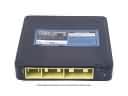 2000 Ford Mustang Engine Control Module
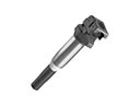 2000 Ford Mustang Ignition Coil
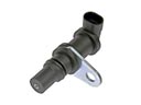 2000 Ford Mustang Crankshaft Position Sensor
 2000 Ford Mustang Horn
 2000 Ford Mustang Speedometer
 2000 Ford Mustang ABS Control Module
 2000 Ford Mustang Air Bag
 2000 Ford Mustang Air Bag Control Module
 2000 Ford Mustang Intake Manifold Temperature Sensor
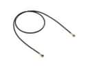 2000 Ford Mustang Speedometer Cable
 2000 Ford Mustang Temperature Sender
 2000 Ford Mustang Window Switch