FordParts
My Garage
My Account
Cart
OEM 2002 Mercury Grand Marquis Intake Manifold
Engine Intake Manifold- Select Vehicle by Model
- Select Vehicle by VIN
Select Vehicle by Model
orMake
Model
Year
Select Vehicle by VIN
For the most accurate results, select vehicle by your VIN (Vehicle Identification Number).
1 Intake Manifold found


2002 Mercury Grand Marquis Intake Manifold Part Number: 1W7Z-9424-AB
$334.83 MSRP: $491.67You Save: $156.84 (32%)Product Specifications- Other Name: Manifold Assembly - Inlet
- Manufacturer Note: One Piece Design
- Replaced by: PU7Z-9424-A
- Base No.: 9424
- Item Weight: 17.00 Pounds
- Item Dimensions: 21.0 x 18.4 x 12.5 inches
- Condition: New
- Fitment Type: Direct Replacement
- SKU: 1W7Z-9424-AB
- Warranty: This genuine part is guaranteed by Ford's factory warranty.
2002 Mercury Grand Marquis Intake Manifold
If you're seeking quality and affordability, look no further than our extensive inventory of genuine 2002 Mercury Grand Marquis Intake Manifold available at FordPartsDeal.com. You can confidently purchase our OEM 2002 Mercury Grand Marquis Intake Manifold as they are supported by the manufacturer's warranty and our hassle-free return policy, alongside the benefit of our fast delivery service.
2002 Mercury Grand Marquis Intake Manifold Parts Q&A
- Q: How to remove the intake manifold on 2002 Mercury Grand Marquis?A: The first step to remove the intake manifold requires disconnecting the power cable from the battery alongside draining the engine coolant system. The first step requires disconnecting the fuel lines and then removing the air cleaner outlet tube. Begin your procedure by taking off the wiper mounting arm together with the pivot shaft while you also detach the drive belt. Place the vehicle on a hoist to disconnect the CKP sensor electrical connector together with the pin-type retainer from the A/C compressor bracket and discard the electrical connector linked to the A/C compressor. Extract the oil bypass filter from its position before disconnecting the oil pressure sensor electrical connector and the power steering pressure (PSP) switch electrical connector. The first step consists of removing the right-hand catalytic converter assembly and separating the exhaust gas recirculation (EGR) tube from contacting the exhaust manifold. The maintenance process requires a vehicle to be lowered to a proper height for disconnecting the electrical connection from the differential pressure feedback EGR system. The eight ignition coil and eight fuel injector electrical wiring connectors must be disconnected. The accelerator cable and speed control actuator cable and throttle return spring need removal before moving all three components away from the EGR tube heat shield area. The first step requires removing bolts from the EGR tube heat shield then disconnecting both the evaporative emissions (EVAP) return tube together with the main chassis vacuum supply hose and EGR valve vacuum supply hose. Disconnect the positive crankcase ventilation (PCV) tube assembly at two points before taking it away, and disconnect the electrical connector from the EGR vacuum regulator solenoid along with the vacuum line from the EVAP canister purge valve. Unplug the generator cable while also removing its electrical connector and harness pin-type retaining clamp before unscrewing the bolts to take out the generator mounting bracket. Detach the upper radiator hose after disconnecting both the idle air control (IAC) valve electric connector and throttle position (TP) sensor connector. Then remove the heater water hose and EGR tube nut that secures the EGR valve. Before removing the bracket please remove the separation of the wiring harness pin-type retainer from the crash bracket followed by separating the LH heated oxygen sensor and the transmission electrical connectors from the wiring bracket. Uncouple all wiring connectors before splitting the transmission harness from the stud and removing its nut and bolt. Drain the bolting material the throttle body requires before pulling out the crash bracket cables. Start by removing the bolt and stud which allow removal of the crash bracket and separating vacuum lines before extracting the vacuum harness. Unfasten the ground connector attached to the right-hand rear stud and the generator harness pin-type retainer fixed to the left-hand front stud. You need to detach first the four studs together with the fuel injectors and fuel injection supply manifold as one unit followed by uninstalling the eight bolts which supports eight ignition coils. Start by removing the bolts of the water outlet adapter then disconnect the cooling sensor electrical connector and take out the water thermostat. The last step includes removing the fuel charging wiring position retainer from the back of the intake manifold and then taking off the bolts and the intake manifold and discarding the intake manifold gaskets while preparing all sealing surfaces for installation.
Related 2002 Mercury Grand Marquis Parts
 2002 Mercury Grand Marquis Fuel Filter
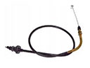 2002 Mercury Grand Marquis Accelerator Cable
 2002 Mercury Grand Marquis Air Filter
 2002 Mercury Grand Marquis Air Filter Box
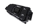 2002 Mercury Grand Marquis Cruise Control Switch
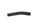 2002 Mercury Grand Marquis Fuel Filler Hose
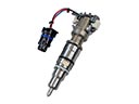 2002 Mercury Grand Marquis Fuel Injector
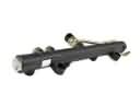 2002 Mercury Grand Marquis Fuel Rail
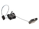 2002 Mercury Grand Marquis Fuel Tank Sending Unit
 2002 Mercury Grand Marquis Fuel Tank Strap
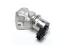 2002 Mercury Grand Marquis Idle Control Valve
 2002 Mercury Grand Marquis Intake Manifold Gasket