FordParts
My Garage
My Account
Cart
OEM 2003 Ford Windstar Shift Interlock Solenoid
Shift Lock Actuator- Select Vehicle by Model
- Select Vehicle by VIN
Select Vehicle by Model
orMake
Model
Year
Select Vehicle by VIN
For the most accurate results, select vehicle by your VIN (Vehicle Identification Number).
1 Shift Interlock Solenoid found


2003 Ford Windstar Lock Actuator Part Number: F2DZ-3Z719-A
$56.22 MSRP: $89.27You Save: $33.05 (38%)Product Specifications- Other Name: Solenoid Assembly; Shift Interlock Solenoid; Interlock Solenoid; Solenoid; Actuator
- Replaces: YC3Z-3Z719-AA
- Base No.: 3Z719
- Item Weight: 0.40 Pounds
- Condition: New
- Fitment Type: Direct Replacement
- SKU: F2DZ-3Z719-A
- Warranty: This genuine part is guaranteed by Ford's factory warranty.
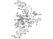
2003 Ford Windstar Shift Interlock Solenoid
If you're seeking quality and affordability, look no further than our extensive inventory of genuine 2003 Ford Windstar Shift Interlock Solenoid available at FordPartsDeal.com. You can confidently purchase our OEM 2003 Ford Windstar Shift Interlock Solenoid as they are supported by the manufacturer's warranty and our hassle-free return policy, alongside the benefit of our fast delivery service.
2003 Ford Windstar Shift Interlock Solenoid Parts Q&A
- Q: How to Service and Repair the Shift Interlock Solenoid on 2003 Ford Windstar?A: Service and repairs of Brake Shift Interlock Actuator require first draining the back up power supply in order to prevent air bag deployment during service. Start the Brake Shift Interlock Actuator service by disconnecting the battery ground cable and waiting for at least one minute and disconnection of any auxiliary batteries and power supplies if present. Start your work by unscrewing the two fasteners which secure the instrument panel lower steering column opening cover and proceed to detach and remove the right-hand instrument panel finish panel. You must unscrew the screws that fasten both the instrument panel opening cover reinforcement and the steering column opening brace. You should position the selector lever indicator cable away from the work area before unscrewing the cable and disconnecting it. The steering column can be lowered after removing four nuts and the bracket. Migrate to extract the shift lock actuator as well as the transmission shift selector position insert through the process of disassembling bolts before separating the steering column components while disconnecting the electrical connector. The installation process ends with reversing the steps used during removal.
Related 2003 Ford Windstar Parts
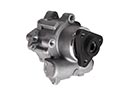 2003 Ford Windstar Power Steering Pump
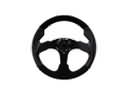 2003 Ford Windstar Steering Wheel
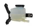 2003 Ford Windstar Power Steering Reservoir
 2003 Ford Windstar Rack & Pinion Bushing
 2003 Ford Windstar Rack And Pinion
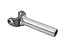 2003 Ford Windstar Slip Yoke
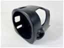 2003 Ford Windstar Steering Column Cover
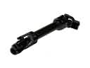 2003 Ford Windstar Steering Shaft
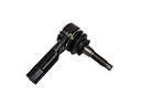 2003 Ford Windstar Tie Rod
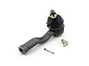 2003 Ford Windstar Tie Rod End
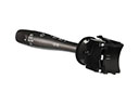 2003 Ford Windstar Turn Signal Switch
 2003 Ford Windstar Upper Steering Column Bearing