FordParts
My Garage
My Account
Cart
OEM 2004 Ford Expedition Fuel Rail
Engine Fuel Rail- Select Vehicle by Model
- Select Vehicle by VIN
Select Vehicle by Model
orMake
Model
Year
Select Vehicle by VIN
For the most accurate results, select vehicle by your VIN (Vehicle Identification Number).
2 Fuel Rails found


2004 Ford Expedition Fuel Rail Part Number: 2L1Z-9F792-EA
Product Specifications- Other Name: Manifold Assembly - Fuel; Manifold Assembly - Fuel Supply
- Base No.: 9F792
- Item Weight: 2.40 Pounds
- Condition: New
- Fitment Type: Direct Replacement
- SKU: 2L1Z-9F792-EA
- Warranty: This genuine part is guaranteed by Ford's factory warranty.

2004 Ford Expedition Fuel Rail Part Number: 2L1Z-9F792-DA
Product Specifications- Other Name: Manifold Assembly - Fuel; Manifold Assembly - Fuel Supply
- Base No.: 9F792
- Item Weight: 2.90 Pounds
- Condition: New
- Fitment Type: Direct Replacement
- SKU: 2L1Z-9F792-DA
- Warranty: This genuine part is guaranteed by Ford's factory warranty.
2004 Ford Expedition Fuel Rail
If you're seeking quality and affordability, look no further than our extensive inventory of genuine 2004 Ford Expedition Fuel Rail available at FordPartsDeal.com. You can confidently purchase our OEM 2004 Ford Expedition Fuel Rail as they are supported by the manufacturer's warranty and our hassle-free return policy, alongside the benefit of our fast delivery service.
2004 Ford Expedition Fuel Rail Parts Q&A
- Q: How to service the Fuel Rail on 2004 Ford Expedition?A: Service of the fuel injection supply manifold needs safety measures that include avoiding smoking or open flames near fuel components because flammable mixtures exist. You must reduce fuel system pressure before you disconnect any fuel lines. The first step should include disconnecting the battery ground cable and performing a partial drainage of the cooling system. Begin by removing the air cleaner outlet pipe then disconnect all accelerator controls through their cable and speed control components along with the return spring. The maintenance process continues with disconnecting all electrical connectors that supply power to idle air control (IAC), throttle position (TP) sensor and exhaust gas recirculation (EGR) vacuum regulator solenoid. The right throttle body vacuum connections need to be removed in addition to the EGR valve vacuum hose and evaporative emission socket (EVAP hose). First place the vacuum harness to the side and then remove the brake booster vacuum tube bracket nut followed by disconnecting the EGR tube fittings. It is important to take out the coolant hoses connecting the intake manifold and to remove the positive crankcase ventilation (PCV) valve located on the valve cover. First detach the throttle body adapter retaining bolts then shift the adapter slightly forward before unconnecting the PCV coolant hose before fully removing the throttle body adapter assembly. Combining fuel tube spring lock coupling and eight fuel injector electrical connector removal enables you to remove the fuel injection supply manifold and injectors from the intake manifold with the help of four bolts. Providers of fuel injector service must eliminate old O-ring seals from injectors before installing new lubricated seals using clean engine oil. The fuel injectors must be inserted into the fuel injection supply manifold before reattaching the injector electrical connectors combined with the fuel tube spring lock coupling. Install the throttle body adapter in position while connecting the PCV coolant hose before adding fresh gasket to install with two-tightening stages. The first stage reaches 9 Nm (80 lb-in) and additional 90-degree turn completes the installation. First connect the brake booster vacuum tube followed by installing its bolt. Then place back the PCV valve and EGR tube and the coolant hose. Connect the vacuum harness to its proper position then reconnect the vacuum connections starting from the EGR vacuum regulator solenoid and EVAP canister purge solenoid then proceed with the EGR vacuum hose and EVAP hose to the throttle body. Connect the vacuum hose after reattaching all remaining vacuum lines that include those directed toward the throttle body right side and fuel pressure regulator. The last step involves reconnecting the EGR vacuum regulator solenoid electrical connector and throttle position sensor electrical connector as well as idle air control electrical connector followed by accelerator controls and air cleaner outlet pipe and cooling system filling and bleeding before reconnecting the battery ground cable.
Related 2004 Ford Expedition Parts
 2004 Ford Expedition Fuel Pump
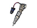 2004 Ford Expedition Fuel Injector
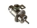 2004 Ford Expedition Fuel Pressure Regulator
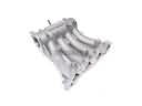 2004 Ford Expedition Intake Manifold
 2004 Ford Expedition Mass Air Flow Sensor
 2004 Ford Expedition Throttle Body
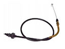 2004 Ford Expedition Accelerator Cable
 2004 Ford Expedition Fuel Filler Neck
 2004 Ford Expedition Fuel Level Sensor
 2004 Ford Expedition Fuel Pump Gasket
 2004 Ford Expedition Fuel Tank Lock Ring
 2004 Ford Expedition Idle Control Valve