FordParts
My Garage
My Account
Cart
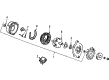
OEM 2004 Ford F-350 Super Duty Voltage Regulator
Adjustable Voltage Regulator- Select Vehicle by Model
- Select Vehicle by VIN
Select Vehicle by Model
orMake
Model
Year
Select Vehicle by VIN
For the most accurate results, select vehicle by your VIN (Vehicle Identification Number).
1 Voltage Regulator found


 Product Specifications
- Other Name: Regulator And Brush; Brush & Holder; Regulator Assembly; Brushes; Regulator; Regulator And Brush Holder Assembly
- Replaces: FODZ-10316-A
- Base No.: 10C359
- Item Weight: 0.40 Pounds
- Item Dimensions: 3.9 x 2.4 x 2.3 inches
- Condition: New
- Fitment Type: Direct Replacement
- SKU: F1DZ-10C359-A
- Warranty: This genuine part is guaranteed by Ford's factory warranty.
2004 Ford F-350 Super Duty Voltage Regulator
If you're seeking quality and affordability, look no further than our extensive inventory of genuine 2004 Ford F-350 Super Duty Voltage Regulator available at FordPartsDeal.com. You can confidently purchase our OEM 2004 Ford F-350 Super Duty Voltage Regulator as they are supported by the manufacturer's warranty and our hassle-free return policy, alongside the benefit of our fast delivery service.
2004 Ford F-350 Super Duty Voltage Regulator Parts Q&A
- Q: How to service and repair the voltage regulator for gasoline-engine generators on 2004 Ford F-350 Super Duty?A: To repair the voltage regulator of gasoline-engine generators, take the generator off and take the voltage regulator off by unscrewing. Unscrew the generator brush and terminal holder, and screw them back into the voltage regulator. Lock it, do not leave out the screw cap and fit the generator again.
Related 2004 Ford F-350 Super Duty Parts
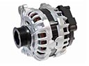 2004 Ford F-350 Super Duty Alternator
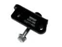 2004 Ford F-350 Super Duty Alternator Bracket
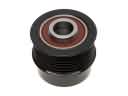 2004 Ford F-350 Super Duty Alternator Pulley
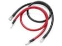 2004 Ford F-350 Super Duty Battery Cable
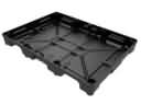 2004 Ford F-350 Super Duty Battery Tray
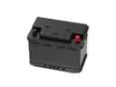 2004 Ford F-350 Super Duty Car Batteries
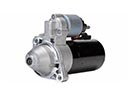 2004 Ford F-350 Super Duty Starter