FordParts
My Garage
My Account
Cart
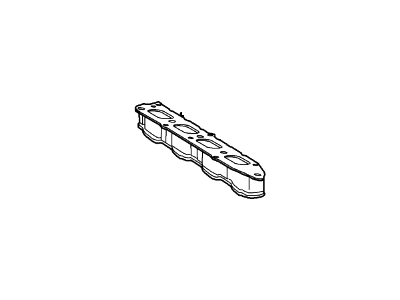
OEM 2005 Ford Thunderbird Intake Manifold
Engine Intake Manifold- Select Vehicle by Model
- Select Vehicle by VIN
Select Vehicle by Model
orMake
Model
Year
Select Vehicle by VIN
For the most accurate results, select vehicle by your VIN (Vehicle Identification Number).
1 Intake Manifold found
2005 Ford Thunderbird Intake Manifold Part Number: 4H2Z-9424-AE
Product Specifications- Other Name: Manifold Assembly - Air Intake
- Replaces: 3W4Z-9424-AE
- Base No.: 9424
- Item Weight: 15.30 Pounds
- Item Dimensions: 17.6 x 15.7 x 13.2 inches
- Condition: New
- Fitment Type: Direct Replacement
- SKU: 4H2Z-9424-AE
- Warranty: This genuine part is guaranteed by Ford's factory warranty.
2005 Ford Thunderbird Intake Manifold
If you're seeking quality and affordability, look no further than our extensive inventory of genuine 2005 Ford Thunderbird Intake Manifold available at FordPartsDeal.com. You can confidently purchase our OEM 2005 Ford Thunderbird Intake Manifold as they are supported by the manufacturer's warranty and our hassle-free return policy, alongside the benefit of our fast delivery service.
2005 Ford Thunderbird Intake Manifold Parts Q&A
- Q: How to service and repair the intake manifold on 2005 Ford Thunderbird?A: The first step for repairing or servicing the intake manifold involves avoiding open flames or smoking around fuel components because flammable mixtures exist. Prior to work begin disconnect the ground cable from the battery after clearing all fuel system pressure. The first steps for servicing the intake manifold involve eliminating the air cleaner outlet pipe together with the cowl panel grille while also disconnecting the fuel supply tube spring lock coupling from the fuel rail. The service procedure starts by removing the Exhaust Gas Recirculation (EGR) system module while also detaching the 6 bolts, cross-vehicle brace and disconnecting these components: Throttle Position (TP) sensor, fuel pressure sensor, throttle body, EVAP hose, fuel rail temperature sensor, crankcase ventilation tube, and vacuum supply tube. The first step is to pull off the vacuum harness retainers and engine wiring harness from engine appearance cover brackets before unfastening the four nuts and two engine appearance cover brackets. Start the repair by disconnecting 8 fuel injector electrical connectors, the radio interference ignition capacitor and removing 4 fuel rail bolts which enables the removal of the fuel rail assembly with injector parts. Life the clips off the assembly to remove 8 fuel injectors while disposing the attached 16 O-ring seals. Take out the intake manifold by unplugging the 2 throttle body coolant tubes, and by removing the 7 bolts along with the 3 studs while discarding the existing gaskets. When installing the system begin by scraping gasket sealing surfaces with a plastic tool before installing new gaskets then the intake manifold followed by securing the 7 bolts and 3 studs which must be tightened to 20 Nm (15 ft. lbs.). Users should connect the throttle body coolant tubes by applying new O-ring seals featuring fuel-resistant material treatment with engine oil to the tubes. The 16 new O-ring seals should then be installed onto the fuel injectors. The fuel rail assembly requires all fuel injectors and clips to be installed before securing it with 4 fuel rail bolts torqued to 10 Nm (89 inch lbs.). Install and tighten the radio interference ignition capacitors with their nuts to 10 Nm (89 inch lbs.), then install the engine wiring harness retainer and authenticate its 2 nuts at 10 Nm (89 inch lbs.). Attach the radio interference ignition capacitor which links to 8 fuel injector electrical connectors before installing the 2 engine appearance cover brackets and putting on their nuts to 6 Nm (53 inch lbs.). Proceed to connect the vacuum supply tube along with crankcase ventilation tube through the fuel rail temperature sensor and EVAP hose and throttle body through the fuel pressure sensor and TP sensor electrical connectors. Finish the installation with bolt installation at 20 Nm (15 ft. lbs.) torque on the cross-vehicle brace while also installing the EGR system module and air cleaner outlet pipe before reconnecting the fuel supply tube spring lock coupling to the fuel rail and then installing the cowl panel grille and reconnecting the battery ground cable.


