FordParts
My Garage
My Account
Cart
OEM 2005 Lincoln Town Car Seat Motor
Car Seat Motor- Select Vehicle by Model
- Select Vehicle by VIN
Select Vehicle by Model
orMake
Model
Year
Select Vehicle by VIN
For the most accurate results, select vehicle by your VIN (Vehicle Identification Number).
3 Seat Motors found


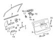
2005 Lincoln Town Car Motor, Driver Side Part Number: 3W1Z-14547-C
Product Specifications- Other Name: Motor Assembly - Seat Adjuster
- Manufacturer Note: LH, With memory
- Position: Driver Side
- Base No.: 617D66
- Item Weight: 8.30 Pounds
- Item Dimensions: 14.8 x 14.3 x 6.1 inches
- Condition: New
- Fitment Type: Direct Replacement
- SKU: 3W1Z-14547-C
- Warranty: This genuine part is guaranteed by Ford's factory warranty.


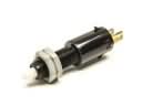
2005 Lincoln Town Car Motor, Passenger Side Part Number: 3W1Z-14547-A
Product Specifications- Other Name: Motor Assembly - Seat Adjuster
- Position: Passenger Side
- Base No.: 14547
- Item Weight: 6.70 Pounds
- Item Dimensions: 13.8 x 4.2 x 12.2 inches
- Condition: New
- Fitment Type: Direct Replacement
- SKU: 3W1Z-14547-A
- Warranty: This genuine part is guaranteed by Ford's factory warranty.
2005 Lincoln Town Car Motor, Driver Side Part Number: 3W1Z-14547-B
$86.10 MSRP: $136.73You Save: $50.63 (38%)Product Specifications- Other Name: Motor Assembly - Seat Adjuster
- Manufacturer Note: LH, Less memory
- Position: Driver Side
- Base No.: 14547
- Item Weight: 6.80 Pounds
- Item Dimensions: 14.1 x 4.1 x 11.9 inches
- Condition: New
- Fitment Type: Direct Replacement
- SKU: 3W1Z-14547-B
- Warranty: This genuine part is guaranteed by Ford's factory warranty.
2005 Lincoln Town Car Seat Motor
If you're seeking quality and affordability, look no further than our extensive inventory of genuine 2005 Lincoln Town Car Seat Motor available at FordPartsDeal.com. You can confidently purchase our OEM 2005 Lincoln Town Car Seat Motor as they are supported by the manufacturer's warranty and our hassle-free return policy, alongside the benefit of our fast delivery service.
2005 Lincoln Town Car Seat Motor Parts Q&A
- Q: How to service and repair the front track seat motor to ensure safety and proper functionality on 2005 Lincoln Town Car?A: Always wear safety glasses for front seat track motor service and repair of vehicles equipped with supplemental restraint systems (SRS) due to their air bag deployment risks and never use memory saver devices. The seat fasteners must receive their proper torque specification in order to stop seat failure and prevent physical harm. A complete SRS depowering procedure must start before any work begins after checking the SRS for operational faults and its complete absence of defects before vehicle return to the customer. First position the seat at the center of the front-and-rear vertical motors. The seat track should be checked by activating the control switch while pressing on the seat cushion; a non-moving seat requires you to replace the seat track assembly. The seatfasteners need to be accessed by moving the seat horizontally and the seat with seat track must be removed after that step. Apply power and ground to the specified pins of the seat track motor electrical connector to modify its horizontal position. Position the seat track motor assembly for extraction correctly before manually rotating the drive tube when powering the horizontal motor. Make notation marks on both outboard and inboard track C-channels to determine correct placements on plastic-coated slide before reinstalling the parts. Disconnect the three memory position sensor electrical connectors after location identification and remove the wire harness, bracket and memory seat module keeping track of wire positions. Remove two nuts and one bolt that secures the memory seat module and then remove two more nuts present at the lift links. A hammer should be used on the drive tube to break it loose from the stub shafts while the inboard track gear stub shaft serves as a clamp point for this operation. Use a screwdriver to remove both the outboard retaining clip and the two bolts fastening the seat track motor assembly to the outboard track. Afterward carefully pry away the outboard track that includes removal of the pinion cage. First remove upper support assembly's support straps followed by seat track motor assembly as well as memory position sensors which need counter-clockwise screw rotation. Install the memory position sensors clockwise by aligning the inboard and outboard tracks so they do not bind with each other. The seat track motor assembly installation must involve application of multi-purpose grease to motor pivots before positioning it onto the upper support assembly with no gaps permitted between the gears. The support straps receive installation at the height adjustment gears' position and you must verify outboard track C-channel and plastic-coated slide index marks alignment before putting the pinion cage to its outboard track position. Set the outboard track into position and adjust the two bolted motor assembly on the outboard track. Finally, add the bracket and two nuts. The user must recheck that index marks are aligned before removing the magnet assembly while confirming that the inboard track C-channel properly lines up with the plastic-coated slide. You should join the seat track motor assembly with the upper support assembly and inboard track by ensuring correct engagement of drive tube and lift links occurs. Check and verify the index marks alignment before installing the inboard track nuts onto the upper support assembly lift links. Install the magnet assembly onto the pivot right after. For the final step install the seat track in the vehicle while making sure the mounting holes have natural alignment and complete steps for memory seats by doing nut installations and electrical connector attachment. Reset the seat track before reinstalling it with the seat while powering up the SRS system and conducting the driver memory seat complete range of motion tests.
Related 2005 Lincoln Town Car Parts
 2005 Lincoln Town Car Brake Light Switch
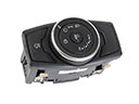 2005 Lincoln Town Car Headlight Switch
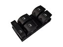 2005 Lincoln Town Car Window Switch
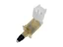 2005 Lincoln Town Car Door Jamb Switch
 2005 Lincoln Town Car Engine Control Module
 2005 Lincoln Town Car Mirror Switch
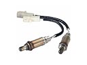 2005 Lincoln Town Car Oxygen Sensors
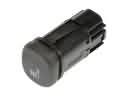 2005 Lincoln Town Car Seat Heater Switch
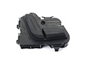 2005 Lincoln Town Car Seat Switch
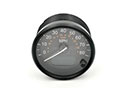 2005 Lincoln Town Car Speedometer
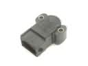 2005 Lincoln Town Car Throttle Position Sensor
 2005 Lincoln Town Car Turn Signal Flasher