FordParts
My Garage
My Account
Cart
OEM 2006 Ford Freestyle Timing Cover
Engine Timing Cover- Select Vehicle by Model
- Select Vehicle by VIN
Select Vehicle by Model
orMake
Model
Year
Select Vehicle by VIN
For the most accurate results, select vehicle by your VIN (Vehicle Identification Number).
1 Timing Cover found

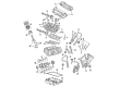
2006 Ford Freestyle Timing Cover, Front Part Number: 5F9Z-6019-BA
Product Specifications- Other Name: Cover - Cylinder Front; Engine Timing Cover; Front Cover
- Position: Front
- Base No.: 6019
- Item Weight: 10.90 Pounds
- Item Dimensions: 13.4 x 13.8 x 4.2 inches
- Condition: New
- Fitment Type: Direct Replacement
- SKU: 5F9Z-6019-BA
- Warranty: This genuine part is guaranteed by Ford's factory warranty.
2006 Ford Freestyle Timing Cover
If you're seeking quality and affordability, look no further than our extensive inventory of genuine 2006 Ford Freestyle Timing Cover available at FordPartsDeal.com. You can confidently purchase our OEM 2006 Ford Freestyle Timing Cover as they are supported by the manufacturer's warranty and our hassle-free return policy, alongside the benefit of our fast delivery service.
2006 Ford Freestyle Timing Cover Parts Q&A
- Q: How to Service and Repair the Engine Front Timing Cover on 2006 Ford Freestyle?A: To fix the engine front cover, maintain cleanliness and go through the following steps: lift the vehicle, disconnect battery and remove several other parts such as crankshaft front seal and A/C compressor. Wipe down clean, replace gaskets and attach bolts to recommended torque. Re-assemble and re-connect everything even the battery.
Related 2006 Ford Freestyle Parts
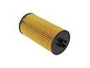 2006 Ford Freestyle Oil Filter
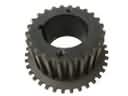 2006 Ford Freestyle Crankshaft Gear
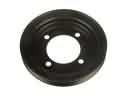 2006 Ford Freestyle Crankshaft Pulley
 2006 Ford Freestyle Cylinder Head Bolts
 2006 Ford Freestyle Dipstick
 2006 Ford Freestyle Dipstick Tube
 2006 Ford Freestyle Drain Plug
 2006 Ford Freestyle Exhaust Valve
 2006 Ford Freestyle Oil Filler Cap
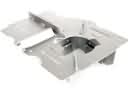 2006 Ford Freestyle Oil Pan Baffle
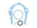 2006 Ford Freestyle Timing Cover Gasket
 2006 Ford Freestyle Valve Stem Seal