FordParts
My Garage
My Account
Cart
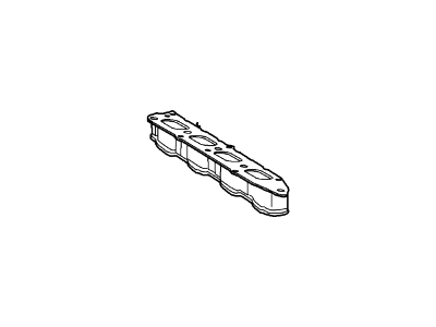
OEM 2006 Lincoln LS Intake Manifold
Engine Intake Manifold- Select Vehicle by Model
- Select Vehicle by VIN
Select Vehicle by Model
orMake
Model
Year
Select Vehicle by VIN
For the most accurate results, select vehicle by your VIN (Vehicle Identification Number).
1 Intake Manifold found
2006 Lincoln LS Intake Manifold Part Number: 4H2Z-9424-AE
Product Specifications- Other Name: Manifold Assembly - Air Intake
- Replaces: 3W4Z-9424-AE
- Base No.: 9424
- Item Weight: 15.30 Pounds
- Item Dimensions: 17.6 x 15.7 x 13.2 inches
- Condition: New
- Fitment Type: Direct Replacement
- SKU: 4H2Z-9424-AE
- Warranty: This genuine part is guaranteed by Ford's factory warranty.
2006 Lincoln LS Intake Manifold
If you're seeking quality and affordability, look no further than our extensive inventory of genuine 2006 Lincoln LS Intake Manifold available at FordPartsDeal.com. You can confidently purchase our OEM 2006 Lincoln LS Intake Manifold as they are supported by the manufacturer's warranty and our hassle-free return policy, alongside the benefit of our fast delivery service.
2006 Lincoln LS Intake Manifold Parts Q&A
- Q: How to service and repair the intake manifold on 2006 Lincoln LS?A: Every servicing or repairing operation on the intake manifold requires following precautions since fuel-related parts possess high flammability. Begin service by draining every liquid from the cooling system before releasing fuel pressure then disconnecting the battery ground cable. Start the intake manifold maintenance procedure by taking off the engine appearance cover together with any detached noise suppressors. Then proceed to take out the air cleaner outlet pipe and the cowl panel grille. Unscrew the fuel rail spring lock coupling from the fuel supply tube before taking out the six bolts and the cross-vehicle brace. The technician should disconnect the throttle position sensor as well as the fuel pressure sensor along with the throttle body electrical connector and the evaporative emissions hose and the fuel rail temperature sensor and the exhaust gas recirculation (EGR) system module electrical connector with its vacuum harness and the EGR system module-to-exhaust manifold tube. The crankcase ventilation tube combined with vacuum supply tube should be removed first while retaining vacuum harnesses and engine wiring harnesses from the engine appearance cover brackets. To disassemble the intake manifold you must first remove the four nuts and two engine appearance cover brackets by disconnecting the eight fuel injectors together with the radio interference ignition capacitor electrical connectors and taking out the two nuts and the engine wiring harness retainer. First disconnect the radio interference ignition capacitor along with its nut while also cutting the two throttle body coolant tubes free. Detach the seven bolts together with three studs in the proper sequence so you can extract the intake manifold along with discarding its gaskets. Begin by cleaning the gasket sealing surface with a plastic scraper before installing new gaskets together with the intake manifold under condition of 20 Nm (15 ft. lbs.) torque when securing the seven bolts and three studs. Begin by connecting the two throttle body coolant tubes then install the radio interference ignition capacitors along with their nuts until they reach a torque of 10 Nm (89 inch lbs.). Complete the installation by attaching the engine wiring harness retainer and its two associated nuts using the same torque setting. Secure the eight fuel injectors together with radio interference ignition capacitor electrical connectors then put on the two engine appearance cover brackets followed by the four nuts which must be tightened to 6 Nm (53 inch lbs.). Set in place the vacuum supply tube followed by crankcase ventilation tube installation and restoration of the engine wiring harness then vacuum harness retainer attachment. Connect all components starting with the EGR system module-to-exhaust manifold tube followed by the EGR system module electrical connector along with vacuum harness then move to connect the fuel rail temperature sensor electrical connector and do the same for the EVAP hose to the intake manifold and all other combinations of electrical connectors and vacuum hoses as listed among the throttle position sensor electrical connector. The six bolts should be installed along with the cross-vehicle brace before tightening them to 20 Nm (15 ft. lbs.). The fuel supply tube requires a spring lock coupling that needs to connect with the fuel rail. Reattach the equipment with the cowl panel grille and air cleaner outlet pipe. Instal the noise suppressor to the intake manifold before adding the engine appearance cover while you reconnect the battery ground wire and complete cooling system filling and bleaching procedures.


