FordParts
My Garage
My Account
Cart
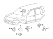
OEM 2007 Lincoln Navigator Air Bag Control Module
SRS Airbag Module- Select Vehicle by Model
- Select Vehicle by VIN
Select Vehicle by Model
orMake
Model
Year
Select Vehicle by VIN
For the most accurate results, select vehicle by your VIN (Vehicle Identification Number).
1 Air Bag Control Module found


2007 Lincoln Navigator Control Module Part Number: 8L1Z-14B321-C
Product Specifications- Other Name: Sensor Assembly - Airbag; Air Bag Control Module; SDM Module; Sensor Assembly - Air Bag
- Replaces: 7L1Z-14B321-E, 8L1Z-14B321-A, 7L1Z-14B321-D, 8L1Z-14B321-B
- Base No.: 14B321
- Item Weight: 1.20 Pounds
- Condition: New
- Fitment Type: Direct Replacement
- SKU: 8L1Z-14B321-C
- Warranty: This genuine part is guaranteed by Ford's factory warranty.
2007 Lincoln Navigator Air Bag Control Module
If you're seeking quality and affordability, look no further than our extensive inventory of genuine 2007 Lincoln Navigator Air Bag Control Module available at FordPartsDeal.com. You can confidently purchase our OEM 2007 Lincoln Navigator Air Bag Control Module as they are supported by the manufacturer's warranty and our hassle-free return policy, alongside the benefit of our fast delivery service.
2007 Lincoln Navigator Air Bag Control Module Parts Q&A
- Q: What Precautions Should Be Taken When Servicing the Air Bag Control Module on 2007 Lincoln Navigator?A: When servicing the Restraints Control Module (RCM), wear safety glasses to prevent injury from air bag deployment. Do not alter the RCM's position with the ignition ON. Inspect for damage after collisions; replace if deformed. Avoid memory savers, handle electronics carefully, and follow installation and diagnostic procedures to ensure proper function.
Related 2007 Lincoln Navigator Parts
 2007 Lincoln Navigator Air Bag
 2007 Lincoln Navigator Air Bag Sensor
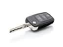 2007 Lincoln Navigator Car Key
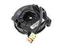 2007 Lincoln Navigator Clock Spring
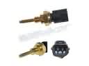 2007 Lincoln Navigator Cylinder Head Temperature Sensor
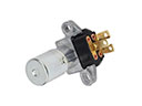 2007 Lincoln Navigator Dimmer Switch
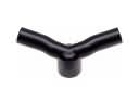 2007 Lincoln Navigator PCV Valve Hose
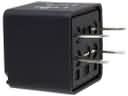 2007 Lincoln Navigator Relay
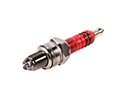 2007 Lincoln Navigator Spark Plug
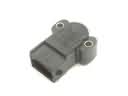 2007 Lincoln Navigator Throttle Position Sensor
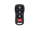 2007 Lincoln Navigator Transmitter
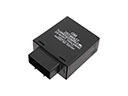 2007 Lincoln Navigator Turn Signal Flasher