My Garage
Cart

OEM 2007 Mercury Mariner Clock Spring

Spiral Cable Clock Spring
  • Select Vehicle by Model
  • Select Vehicle by VIN
Select Vehicle by Model
Make
Model
Year
or
Select Vehicle by VIN
For the most accurate results, select vehicle by your VIN (Vehicle Identification Number).

1 Clock Spring found

  • 2007 Mercury Mariner Clock Spring - 5L8Z-14A664-AB
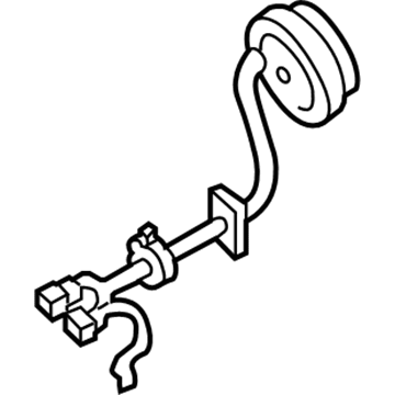
    2007 Mercury Mariner Clock Spring Diagram - 5L8Z-14A664-AB
    View related parts

    2007 Mercury Mariner Clockspring Part Number: 5L8Z-14A664-AB

    $166.33 MSRP: $256.68
    You Save: $90.35 (36%)
    Ships in 1-3 Business Days
    ADD TO CART
    Product Specifications
    • Other Name: Cover And Contact Plate Assembly; Air Bag Clockspring
    • Replaces: 5L8Z-14A664-AA
    • Base No.: 14A664
    • Item Weight: 1.00 Pounds
    • Item Dimensions: 5.6 x 4.4 x 5.1 inches
    • Condition: New
    • Fitment Type: Direct Replacement
    • SKU: 5L8Z-14A664-AB
    • Warranty: This genuine part is guaranteed by Ford's factory warranty.
    More Info
    Fits the following 2007 Mercury Mariner Submodels:
    • Base, Convenience, Hybrid, Luxury, Premier | 4 Cyl 2.3 L FULL HYBRID EV-GAS (FHEV), 4 Cyl 2.3 L GAS, 6 Cyl 3.0 L GAS

2007 Mercury Mariner Clock Spring

If you're seeking quality and affordability, look no further than our extensive inventory of genuine 2007 Mercury Mariner Clock Spring available at FordPartsDeal.com. You can confidently purchase our OEM 2007 Mercury Mariner Clock Spring as they are supported by the manufacturer's warranty and our hassle-free return policy, alongside the benefit of our fast delivery service.

2007 Mercury Mariner Clock Spring Parts Q&A

  • Q: What Precautions Should Be Taken When Servicing the Clock Spring Assembly on 2007 Mercury Mariner?
    A: Safety glasses must be worn while servicing the Clock Spring assembly to prevent injuries from air bag activation and refrain from using memory saver devices. A warning lamp in the air bag appears when the restraints control module (RCM) fuse is extracted during ignition ON but this situation is normal and indicates no system malfunction. First test that the SRS functions without faults before vehicle return to customer while new part replacement fixes any issue that remains after reinstallation of original components and diagnostic rechecking. The first step should involve disabling the system with straight road wheels in position. Begin by taking out the steering wheel followed by setting the tilt steering column in the downward position if the vehicle has it and then free the retaining tabs on the upper steering column shroud. Let the column move freely upward without fixing it before taking out the three screws which secure the lower steering column shroud. Apply two pieces of masking tape on the Clock Spring to avoid rotation during its disassembly procedure. Safely remove the three Clock Spring screws while keeping the component in its removal position and disconnect the two electrical connectors before taking out the Clock Spring. Apply steady pressure to the Clock Spring outer housing when recentering its rotor by rotating it clockwise until you feel resistance stop. Turn the Clock Spring counterclockwise to reveal the yellow indicator at the 1 o'clock window and match the rotor arrow with the housing arrow point-to-point. Use the electrical connectors to attach the Clock Spring while rotating the rotor slightly to achieve proper steering column alignment where the large slot faces the large tab and small slot faces the small tab. Then install all three Clock Spring screws before tape removal for used parts and inserting retaining pins for new parts. Secure the lower steering column shroud through its screws afterward adjust the steering column to its downward position before locking it then attach the upper shroud while engaging its retaining tabs. To finish the procedure reinstall the steering wheel and complete system powering.