FordParts
My Garage
My Account
Cart
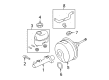
OEM 2008 Ford F-150 Brake Booster
Brake Power Booster- Select Vehicle by Model
- Select Vehicle by VIN
Select Vehicle by Model
orMake
Model
Year
Select Vehicle by VIN
For the most accurate results, select vehicle by your VIN (Vehicle Identification Number).
1 Brake Booster found


2008 Ford F-150 Brake Booster Part Number: 8L3Z-2005-B
Product Specifications- Other Name: Booster Assembly - Brake; Power Brake Booster; Booster Assembly
- Replaces: 6L3Z-2005-BB
- Base No.: 6L3Z-2005-AA
- Item Weight: 11.00 Pounds
- Item Dimensions: 15.3 x 12.9 x 13.1 inches
- Condition: New
- Fitment Type: Direct Replacement
- SKU: 8L3Z-2005-B
- Warranty: This genuine part is guaranteed by Ford's factory warranty.
2008 Ford F-150 Brake Booster
If you're seeking quality and affordability, look no further than our extensive inventory of genuine 2008 Ford F-150 Brake Booster available at FordPartsDeal.com. You can confidently purchase our OEM 2008 Ford F-150 Brake Booster as they are supported by the manufacturer's warranty and our hassle-free return policy, alongside the benefit of our fast delivery service.
2008 Ford F-150 Brake Booster Parts Q&A
- Q: How to service and repair the vacuum brake booster on 2008 Ford F-150?A: The first step to repair or service the vacuum brake booster requires disconnecting the electrical connector of the brake fluid level warning switch. All 4.6L engine vehicles require their brake booster vacuum hose to flow over the exhaust gas recirculation (EGR) valve to avoid damage while you disconnect the vacuum hose from the brake booster vacuum fitting. The service requires removing and setting aside the master cylinder after detaching its two mounting nuts which should be tightened to 25 Nm (18 lb-ft) during reinstallation. It is essential to remove the stop lamp switch and speed control deactivator switch after compressing their plungers while the brake pedal remains at rest in order to protect them from damage. You should start by removing the speed control deactivator switch before untightening the redundant self-locking pin cover and the self-locking pin. Position the stop lamp switch and booster rod along with the bushing in a different space from the brake pedal pin before removing the four brake booster nuts that require tightening to 25 Nm (18 lb-ft) when reinstalling. The installation of stop lamp switches and speed control deactivator switches requires a brake pedal at rest position while the push rod from the booster is attached to prevent any damage and allow correct adjustment. The complete installation process will begin by reversing all previous disassembly measures.
Related 2008 Ford F-150 Parts
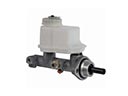 2008 Ford F-150 Brake Master Cylinder
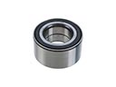 2008 Ford F-150 Wheel Bearing
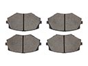 2008 Ford F-150 Brake Pads
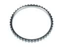 2008 Ford F-150 ABS Reluctor Ring
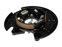 2008 Ford F-150 Brake Backing Plate
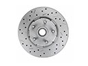 2008 Ford F-150 Brake Disc
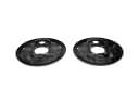 2008 Ford F-150 Brake Dust Shields
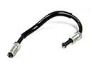 2008 Ford F-150 Brake Line
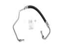 2008 Ford F-150 Hydraulic Hose
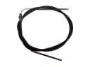 2008 Ford F-150 Parking Brake Cable
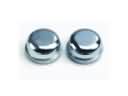 2008 Ford F-150 Wheel Bearing Dust Cap
 2008 Ford F-150 Wheel Hub