FordParts
My Garage
My Account
Cart
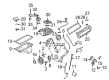
OEM 2008 Ford F-250 Super Duty Intake Manifold
Engine Intake Manifold- Select Vehicle by Model
- Select Vehicle by VIN
Select Vehicle by Model
orMake
Model
Year
Select Vehicle by VIN
For the most accurate results, select vehicle by your VIN (Vehicle Identification Number).
2 Intake Manifolds found


2008 Ford F-250 Super Duty Intake Manifold Part Number: 5L1Z-9424-A
Product Specifications- Other Name: Manifold Assembly - Inlet; Engine Intake Manifold; Lower Manifold
- Replaces: 5L1Z-9424-AB
- Base No.: 9424
- Item Weight: 22.10 Pounds
- Item Dimensions: 23.5 x 19.4 x 15.8 inches
- Condition: New
- Fitment Type: Direct Replacement
- SKU: 5L1Z-9424-A
- Warranty: This genuine part is guaranteed by Ford's factory warranty.


2008 Ford F-250 Super Duty Intake Manifold Part Number: 8C3Z-9424-A
Product Specifications- Other Name: Manifold Assembly - Inlet
- Base No.: 9424
- Item Weight: 14.40 Pounds
- Item Dimensions: 29.9 x 21.8 x 9.3 inches
- Condition: New
- Fitment Type: Direct Replacement
- SKU: 8C3Z-9424-A
- Warranty: This genuine part is guaranteed by Ford's factory warranty.
2008 Ford F-250 Super Duty Intake Manifold
If you're seeking quality and affordability, look no further than our extensive inventory of genuine 2008 Ford F-250 Super Duty Intake Manifold available at FordPartsDeal.com. You can confidently purchase our OEM 2008 Ford F-250 Super Duty Intake Manifold as they are supported by the manufacturer's warranty and our hassle-free return policy, alongside the benefit of our fast delivery service.
2008 Ford F-250 Super Duty Intake Manifold Parts Q&A
- Q: How to install the intake manifold with the body on on 2008 Ford F-250 Super Duty?A: The installation of the intake manifold with the body requires placing the gasket locating tabs up and toward engine center to stop leaks. Install the intake manifold gaskets while also putting back the fuel injector return tube if it was taken out. You must first loosely install all bolts before tightening them to 11 Nm (97 lb-inch) torque values in two separate rounds. When installing banjo bolts for the intake manifold select ones with green hex heads because they do not contain check valves; the proper version should allow visual access from the inner end. Install new copper sealing washers onto the banjo bolts located at the cylinder heads before torqueing them to 38 Nm (28 lb-ft). Secure the fuel injector return tube bolts until reaching 13 Nm (115 lb-inch) and secure the nut at the fuel injector return tube bracket to 11 Nm (97 lb-inch). You should install the fuel filter module through its bolts which require tightening to 13 Nm (115 lb-inch) and after that reutilize green hex head banjo bolts together with new copper sealing washers while you tighten the M14 banjo bolt to 47 Nm (35 lb-ft) and the M12 banjo bolt to 38 Nm (28 lb-ft). Place the RH heater supply tube with an updated O-ring seal that requires tightening both bolt and nut to reach 13 Nm (115 lb-inch). Secure the glow plug module bracket with its bolts at 13 Nm (115 lb-inch) torque value and maintain the engine harness between the bracket and heater supply tube. Secure the glow plug module electrical connectors with pin-type retainers, then connect the LH fuel charging harness electrical connector with its pushpin retainer followed by the EOT and EOP sensor electrical connectors and the ECT sensor electrical connector and wire retainer, fuel temperature sensor electrical connector with retainer and the RH fuel charging harness electrical connector with IAT2 and MAP sensor electrical connectors. Attach the TB electrical connector after you install a press-in-place gasket along with an intake throttle adapter along with loosely installed bolts. The installation of a fresh horizontal EGR cooler gasket becomes essential before mounting the vertical EGR cooler assembly while applying loose bolt tightening. You should install the vertical EGR cooler gasket and position the stud before tightening it to 31 Nm (23 lb-ft). Then finish installation by applying torque to the vertical EGR cooler nut and bolt for the same torque specification. Begin by securing the retaining clip and nut on the stud with 12 Nm (106 lb-inch) torque and connect the EGRT sensor electrical connector with EGR cooler hose and both retaining clips at 4 Nm (35 lb-inch). The EGR cooler bellows should remain straight while you check the vertical EGR cooler inlet for damage before securing its nuts with 31 Nm (23 lb-ft) torque. The installation process starts by using constant tension worm gear clamps for coolant hoses and adding a new clamp on the EGR cooler hose before connecting it properly while tightening the clamp at 4 Nm (35 lb-inch). The EGR cooler vertical bracket bolts need tightening with M8 bolts to 31 Nm (23 lb-ft) torque and the M10 bolt needs to reach 62 Nm (46 lb-ft) torque. Fasten the intake throttle adapter bolts to 10 Nm (89 lb-inch) before installing the EGR cooler coolant tube with its new O-ring seal which should be tightened to 10 Nm (89 lb-inch). Put back the FEAD assembly before installing nuts and bolts which need to be tightened to 47 Nm (35 lb-ft). Reposition the power steering pump by placing the pressure tube retainer onto the retaining stud before bolting it to 25 Nm (18 lb-ft) while also torquing the power steering hose retaining nut to the same value. Follow the installation process by using a back up wrench on high-pressure fuel pump fittings while adding new copper sealing washers and installing the supply and return tubes with respective nuts tightened to 38 Nm (28 lb-ft) and supply tube retaining nuts set to 11 Nm (97 lb-inch). Fit the pin-type retainer and insert the high-pressure fuel injection pump electrical connector while connecting the fuel injector return tube to the check valve and tighten it to 28 Nm (21 lb-ft). Position the glow plug module heat shield first before installing new pushnuts while you install the fuel rail supply tube retainers who have a torque limit of 13 Nm (115 lb-inch). First install the heater hose onto the heater supply tube while adding a fresh press-in-place gasket followed by assembling and tightening the crankcase vent oil separator with bolts to 13 Nm (115 lb-inch). The crankcase vent oil separator tube installation process involves connecting it to its tube. Then add the A/C belt if present along with the accessory drive belt and finally connect the cooling fan stator. Install the high-pressure fuel injection pump heat shield into the vehicle and secure its two center bolts by torquing them to 13 Nm (115 lb-inch). Screw the fuel tube bracket in place along with the ground strap before tightening the high-pressure fuel pump shield bolt to 13 Nm and the fuel line bracket nuts to 7 Nm while remaining fasteners should reach 13 Nm. You should place the EGR-OC pipe inside the vehicle before installing the turbocharger.
Related 2008 Ford F-250 Super Duty Parts
 2008 Ford F-250 Super Duty Air Duct
 2008 Ford F-250 Super Duty Air Filter
 2008 Ford F-250 Super Duty Fuel Filler Neck
 2008 Ford F-250 Super Duty Fuel Filter
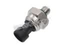 2008 Ford F-250 Super Duty Fuel Pressure Sensor
 2008 Ford F-250 Super Duty Fuel Pump
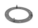 2008 Ford F-250 Super Duty Fuel Pump Gasket
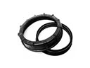 2008 Ford F-250 Super Duty Fuel Pump Seal
 2008 Ford F-250 Super Duty Fuel Pump Tank Seal
 2008 Ford F-250 Super Duty Fuel Tank Sending Unit
 2008 Ford F-250 Super Duty Fuel Tank Strap
 2008 Ford F-250 Super Duty Intake Manifold Gasket