FordParts
My Garage
My Account
Cart
OEM 2009 Ford E-250 Neutral Safety Switch
Transmission Neutral Safety Switch- Select Vehicle by Model
- Select Vehicle by VIN
Select Vehicle by Model
orMake
Model
Year
Select Vehicle by VIN
For the most accurate results, select vehicle by your VIN (Vehicle Identification Number).
1 Neutral Safety Switch found


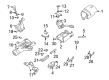
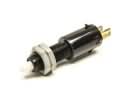
2009 Ford E-250 Neutral Safety Switch Part Number: F7LZ-7F293-AB
$57.48 MSRP: $91.27You Save: $33.79 (38%)Product Specifications- Other Name: Sensor - Manual Lever Position; Transmission Range Sensor; Transmiss Range Sensor; Range Sensor; Back-Up & Neutral Safety Switch; Sensor - Manual Lever Position - Mlps
- Replaces: F7LZ-7F293-AA
- Base No.: 7F293
- Item Weight: 0.50 Pounds
- Item Dimensions: 8.3 x 7.6 x 7.8 inches
- Condition: New
- Fitment Type: Direct Replacement
- SKU: F7LZ-7F293-AB
- Warranty: This genuine part is guaranteed by Ford's factory warranty.
2009 Ford E-250 Neutral Safety Switch
If you're seeking quality and affordability, look no further than our extensive inventory of genuine 2009 Ford E-250 Neutral Safety Switch available at FordPartsDeal.com. You can confidently purchase our OEM 2009 Ford E-250 Neutral Safety Switch as they are supported by the manufacturer's warranty and our hassle-free return policy, alongside the benefit of our fast delivery service.
2009 Ford E-250 Neutral Safety Switch Parts Q&A
- Q: How to service and repair the Neutral Safety Switch for the 4R70E/4R75E on 2009 Ford E-250?A: To install the Transmission Position Switch/Sensor 4R70E/4R75E, make sure the car is in neutral, and then disconnect the TR sensor connector and selector lever cable, then remove the manual control lever. Install TR sensor making sure it is aligned and tighten bolts. Redo the cables and reconnect the manual control lever.
Related 2009 Ford E-250 Parts
 2009 Ford E-250 Brake Light Switch
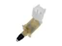 2009 Ford E-250 Door Jamb Switch
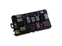 2009 Ford E-250 Fuse
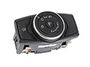 2009 Ford E-250 Headlight Switch
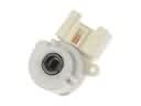 2009 Ford E-250 Ignition Switch
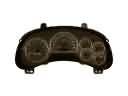 2009 Ford E-250 Instrument Cluster
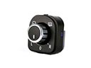 2009 Ford E-250 Mirror Switch
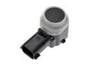 2009 Ford E-250 Parking Assist Distance Sensor
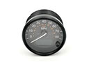 2009 Ford E-250 Speedometer
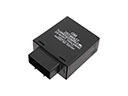 2009 Ford E-250 Turn Signal Flasher
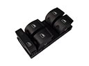 2009 Ford E-250 Window Switch
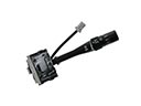 2009 Ford E-250 Wiper Switch