FordParts
My Garage
My Account
Cart
OEM Ford E-250 Econoline Clock Spring
Spiral Cable Clock Spring- Select Vehicle by Model
- Select Vehicle by VIN
Select Vehicle by Model
orMake
Model
Year
Select Vehicle by VIN
For the most accurate results, select vehicle by your VIN (Vehicle Identification Number).
9 Clock Springs found


Ford E-250 Econoline Clockspring Part Number: F8UZ-14A664-DA
$97.10 MSRP: $141.33You Save: $44.23 (32%)Ships in 1-2 Business Days
Ford E-250 Econoline Clockspring Part Number: F7UZ-14A664-EC
$103.06 MSRP: $150.02You Save: $46.96 (32%)Ships in 1-3 Business Days


Ford E-250 Econoline Clockspring Part Number: F3UZ-14A664-B


Ford E-250 Econoline Clockspring Part Number: F2UZ-14A664-B
Ford E-250 Econoline Clockspring Part Number: F5UZ-14A664-NB
Ford E-250 Econoline Clockspring Part Number: F5UZ-14A664-B
Ford E-250 Econoline Clockspring Part Number: F5UZ-14A664-A
Ford E-250 Econoline Clockspring Part Number: F3UZ-14A664-A
Ford E-250 Econoline Clockspring Part Number: F2UZ-14A664-D
Ford E-250 Econoline Clock Spring
OEM Clock Spring boasts unmatched quality. Each part goes through full quality checks. They adhere to Ford's official factory standards. These steps remove flaws and inconsistencies. So you can get Clock Spring with long life and a perfect fit. Come to our website and find genuine Ford E-250 Econoline parts. We keep a wide inventory of OEM E-250 Econoline parts at the highly affordable prices. It's easy to search, compare, and pick what you need. You'll love the clear info and simple checkout. We offer top-rated customer service, and we reply fast. We also ship promptly to ensure your order arrives on time.
Ford E-250 Econoline Clock Spring Parts and Q&A
- Q: How to Service and Repair the Clock Spring for the Air Bag Sliding Contact on Ford E-250 Econoline?A:Dealing with the air bag sliding contact needs proper execution that begins by wearing safety glasses and depowering the system. First detach the driver air bag module then free its retaining clips before removing the steering column opening lower finish panel and its reinforcement. The electrical connector needs removal along with the screw that holds the data link connector. After this, remove all bolts and also discard the reinforcement. Remove the steering wheel only when the wheels point straight ahead after disconnecting both Clock Spring electrical connections at the base of the steering column. Begin by twisting and removing the tilt wheel handle with its shank when present before taking off the lower steering column shroud through screw removal. The ignition switch lock cylinder needs removal when placing it in the RUN position followed by pressing on the cylinder release tab then pulling it outward. Working on the steering column requires users to first remove the upper shroud then place two tape strips across the Clock Spring before taking out the warning indicator switch. The technician disconnects the Clock Spring electrical connector before separating the air bag electrical connector from the bracket. During this process the technician should pry free the retaining clips until the Clock Spring can be removed through the instrument panel (04320). During Clock Spring installation for new parts always pull the key out from its central position yet prevent any rotor movement. Begin by keeping the outer housing still then turn the rotor clockwise while feeling the resistance before counterclockwise rotation of the same 2.25 turns to achieve the center position. When using the same Clock Spring in repairs slide the flat sections of the component towards the steering column but keep the tape static while doing so until the retaining tabs secure into place. The installation process requires pressure on the six, twelve and three positions to position the Clock Spring before wiring every set inside clips and establishing an electrical connection. Guidelines show to first install the key-in-ignition warning indicator switch after which you should only remove the yellow anti-rotation tab on new Clock Spring installation before putting in the upper steering column shroud. Check that the ignition switch lock cylinder fully enters the steering column housing after insertion before testing its operational function by rotating the cylinder. After installing the lower steering column shroud one should add the steering column opening cover and finally position the tilt wheel handle for the model with this feature. Begin by putting into place the reinforcement for the lower finish panel of the steering column opening and proceed with bolt installation and pin-type electrical connector and data link connector screw attachment. Follow all safety warnings while installing the steering wheel with the finishing panel of the steering column opening. The driver air bag module must be placed into the steering wheel before connecting electrical connectors for the horn and driver air bag module and then installing two bolts together with back cover plugs for system reactivation.

Related Ford E-250 Econoline Parts
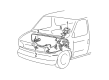
 Ford E-250 Econoline Air Bag Control Module
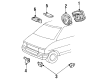
 Ford E-250 Econoline Air Bag Sensor
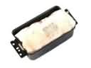 Ford E-250 Econoline Airbag
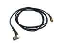 Ford E-250 Econoline Antenna Cable
 Ford E-250 Econoline Coolant Temperature Sensor
 Ford E-250 Econoline Distributor
 Ford E-250 Econoline Distributor Cap
 Ford E-250 Econoline Ignition Coil
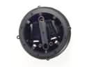 Ford E-250 Econoline Mirror Actuator
 Ford E-250 Econoline Mirror Switch
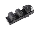 Ford E-250 Econoline Power Window Switch
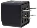 Ford E-250 Econoline Relay