FordParts
My Garage
My Account
Cart
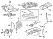
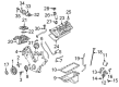
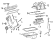
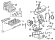
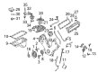
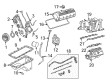
OEM Ford F-150 Heritage Intake Manifold
Engine Intake Manifold- Select Vehicle by Model
- Select Vehicle by VIN
Select Vehicle by Model
orMake
Model
Year
Select Vehicle by VIN
For the most accurate results, select vehicle by your VIN (Vehicle Identification Number).
10 Intake Manifolds found


Ford F-150 Heritage Intake Manifold, Upper Part Number: 1L3Z-9424-AA
$59.31 MSRP: $86.33You Save: $27.02 (32%)


Ford F-150 Heritage Intake Manifold Part Number: 2L1Z-9424-AA
$324.61 MSRP: $476.67You Save: $152.06 (32%)

Ford F-150 Heritage Intake Manifold, Lower Part Number: 4L3Z-9424-AA


Ford F-150 Heritage Intake Manifold Part Number: 3L3Z-9424-HA

Ford F-150 Heritage Intake Manifold, Lower Part Number: 5L3Z-9424-CA

Ford F-150 Heritage Intake Manifold Part Number: 4L3Z-9424-BA

Ford F-150 Heritage Intake Manifold, Upper Part Number: 3L3Z-9424-DA
Ford F-150 Heritage Intake Manifold, Lower Part Number: 2L1Z-9424-BC


Ford F-150 Heritage Intake Manifold, Upper Part Number: 1L3Z-9424-DA
Ford F-150 Heritage Intake Manifold, Lower Part Number: 1L3Z-9424-CA
Ford F-150 Heritage Intake Manifold
OEM Intake Manifold boasts unmatched quality. Each part goes through full quality checks. They adhere to Ford's official factory standards. These steps remove flaws and inconsistencies. So you can get Intake Manifold with long life and a perfect fit. Come to our website and find genuine Ford F-150 Heritage parts. We keep a wide inventory of OEM F-150 Heritage parts at the highly affordable prices. It's easy to search, compare, and pick what you need. You'll love the clear info and simple checkout. We offer top-rated customer service, and we reply fast. We also ship promptly to ensure your order arrives on time.
Ford F-150 Heritage Intake Manifold Parts and Q&A
- Q: How to service and repair the intake manifold on a 4.6L engine on Ford F-150 Heritage?A:A proper approach to service and repair the intake manifold of a 4.6L engine starts with disconnecting the battery ground cable while removing the air cleaner outlet pipe. The first step is to drain the engine cooling system followed by clamping and sliding the hose clamp to take away the upper radiator hose. The service requires removing three components from the Throttle Body cam by disconnecting the accelerator cable and speed control actuator cable and removing the accelerator return spring. First disconnect the bolts on the accelerator cable bracket then place all these elements aside. The procedure requires removal of the main vacuum harness together with the Idle Air Control (IAC) fresh air hose, differential pressure feedback Exhaust Gas Recirculation (EGR) sensor electrical connector, and EGR vacuum regulator solenoid connections. The service technician should separate the electrical connections of IAC and TP sensor while also detaching the EGR valve vacuum hose, the EVAP canister purge valve hose and its associated vacuum lines from the fuel pressure regulator and EVAP canister purge valve. Drain the nut which disconnects the brake booster tube before setting the bracket and tube aside while placing the crankcase ventilation hose to the side. First disconnect the vacuum hoses from the EGR valve tube then position the exhaust manifold to EGR valve tube aside before disconnecting the upper fitting while loosening the lower fitting. Disconnect all spring-lock fuel hose couplings together with heater hose and heated throttle body inlet hose and finally the PCV hose itself. You should disconnect the heated PCV fitting hose followed by removing the throttle body adapter while discarding the gasket and checking throttle body and adapter for potential damage. Initialize this process by removing the four bolts to let you advance the throttle body adapter slightly. Detach the eight Ignition Coils and the eight fuel injectors after removing the bolts and power steering reservoir upper mounting bracket. To access the engine components the technician should first deviate the belt tensioner clockwise then remove the bolts from the generator upper mount attached to the Alternator pulley followed by the lower mount generator bolts which exit from the generator to place it out of the way. Separate the bolts from the Thermostat housing but discard both components and the O-ring seal while removing the nine bolts to gain access to the intake manifold assembly which requires lifting for disconnecting its tuning valve electrical connector before disposal of gaskets followed by inspecting for damage. The first step for installation requires a plastic scraper to clean all sealing surfaces before positioning new intake manifold gaskets and the upper intake manifold with loose nine bolts. Install the thermostat with new O-ring seal after connecting the intake manifold tuning valve electrical connector then secure the 11 thermostat housing bolts by first tightening them to 2Nm (18 inch lbs.) and second to 25 Nm (18 ft. lbs.). Place the generator in position then begin attaching lower mounting bolts and proceed to install upper mounting bracket and bolts. Tightly rotate the belt tensioning tool clockwise to put on the accessory Drive Belt according to the routing directions on the radiator upper air deflector. Attach eight fuel injector electrical connectors to their respective locations before mounting the eight ignition coils. Start by placing the power steering reservoir upper mounting bracket followed by its bolts until tight then move onto position the throttle body adapter followed by attaching the heated PCV fitting hose using a new gasket with throttle body adapter bolts. First prepare the heated PCV fitting hose and heater hose and exhaust manifold-to-EGR valve tube by hand-tightening fittings before final installation of upper and lower fittings. You must connect the fuel hose spring lock couplings then add the brake booster vacuum tube together with its bracket before installing the nut. Attachment of vacuum harness should come first followed by connecting the EVAP canister purge valve vacuum hose then the vacuum hoses going to the EGR valve tube followed by the fuel pressure regulator vacuum hose and the EVAP canister purge valve hose finally and the EGR valve vacuum hose. The next step includes linking the TP sensor and IAC electrical connectors and the EGR vacuum regulator solenoid connections and the IAC fresh air hose and differential pressure feedback EGR sensor electrical connector, then finish with the main vacuum harness connection. The accelerator cable bracket must be installed with bolts after connecting the throttle body cam to all accelerator controls and their respective components such as cable and speed control actuator cable with throttle return spring. The last step requires connection of the upper radiator hose before clamping it down while installing the air cleaner outlet pipe followed by battery ground cable reconnection to complete engine cooling system filling and bleeding.

Related Ford F-150 Heritage Parts
 Ford F-150 Heritage Air Filter
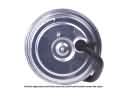 Ford F-150 Heritage Cruise Control Servo
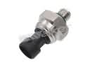 Ford F-150 Heritage Fuel Pressure Sensor
 Ford F-150 Heritage Fuel Pump
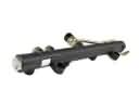 Ford F-150 Heritage Fuel Rail
 Ford F-150 Heritage Fuel Tank
 Ford F-150 Heritage Fuel Tank Strap
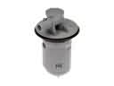 Ford F-150 Heritage Fuel Tank Vent Valve
 Ford F-150 Heritage Gas Cap
 Ford F-150 Heritage Intake Manifold Gasket
 Ford F-150 Heritage Throttle Body
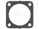 Ford F-150 Heritage Throttle Body Gasket