FordParts
My Garage
My Account
Cart
OEM Ford F-250 Super Duty Rocker Arm
Engine Rocker Arm- Select Vehicle by Model
- Select Vehicle by VIN
Select Vehicle by Model
orMake
Model
Year
Select Vehicle by VIN
For the most accurate results, select vehicle by your VIN (Vehicle Identification Number).
18 Rocker Arms found


Ford F-250 Super Duty Rocker Arms Part Number: 3L3Z-6564-A
$23.13 MSRP: $33.67You Save: $10.54 (32%)Ships in 1 Business Day


Ford F-250 Super Duty Rocker Arms Part Number: F8AZ-6564-AA
$18.09 MSRP: $26.33You Save: $8.24 (32%)Ships in 1 Business Day


Ford F-250 Super Duty Rocker Arms Part Number: 8C3Z-6564-B
$61.09 MSRP: $89.37You Save: $28.28 (32%)Ships in 1 Business Day


Ford F-250 Super Duty Rocker Arms Part Number: 8C3Z-6564-C
$62.82 MSRP: $91.90You Save: $29.08 (32%)Ships in 1 Business Day

Ford F-250 Super Duty Rocker Arms, Passenger Side Part Number: AL3Z-6564-EB
$133.97 MSRP: $195.00You Save: $61.03 (32%)Ships in 1-3 Business Days


Ford F-250 Super Duty Rocker Arms Part Number: AL3Z-6564-AA
$48.00 MSRP: $68.67You Save: $20.67 (31%)Ships in 1 Business Day


Ford F-250 Super Duty Rocker Arms Part Number: F4TZ-6564-B
$70.83 MSRP: $103.81You Save: $32.98 (32%)Ships in 1-3 Business Days

Ford F-250 Super Duty Rocker Arms Part Number: 3C3Z-6564-BB
$98.24 MSRP: $136.19You Save: $37.95 (28%)Ships in 1-2 Business Days
Ford F-250 Super Duty Rocker Arms Part Number: LC3Z-6A585-E
$60.21 MSRP: $101.09You Save: $40.88 (41%)
Ford F-250 Super Duty Rocker Arms Part Number: LC3Z-6A585-F
$64.92 MSRP: $103.09You Save: $38.17 (38%)Ships in 1-2 Business Days
Ford F-250 Super Duty Rocker Arms, Passenger Side Part Number: AL3Z-6564-DB
$131.68 MSRP: $191.67You Save: $59.99 (32%)Ships in 1-3 Business Days
Ford F-250 Super Duty Rocker Arms, Driver Side Part Number: AL3Z-6564-CB
$133.97 MSRP: $195.00You Save: $61.03 (32%)Ships in 1-2 Business Days
Ford F-250 Super Duty Rocker Arms, Driver Side Part Number: AL3Z-6564-BB
$133.97 MSRP: $195.00You Save: $61.03 (32%)Ships in 1-3 Business Days
Ford F-250 Super Duty Rocker Arms Part Number: PC3Z-6564-A
$43.17 MSRP: $62.83You Save: $19.66 (32%)Ships in 1-2 Business Days


Ford F-250 Super Duty Rocker Arms Part Number: 3C3Z-6564-AB
$100.65 MSRP: $139.52You Save: $38.87 (28%)Ford F-250 Super Duty Rocker Shaft Part Number: AL3Z-6564-EA


Ford F-250 Super Duty Rocker Shaft Part Number: AL3Z-6564-CA
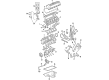
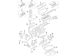
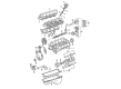
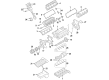
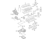
Ford F-250 Super Duty Rocker Arm
OEM Rocker Arm boasts unmatched quality. Each part goes through full quality checks. They adhere to Ford's official factory standards. These steps remove flaws and inconsistencies. So you can get Rocker Arm with long life and a perfect fit. Come to our website and find genuine Ford F-250 Super Duty parts. We keep a wide inventory of OEM F-250 Super Duty parts at the highly affordable prices. It's easy to search, compare, and pick what you need. You'll love the clear info and simple checkout. We offer top-rated customer service, and we reply fast. We also ship promptly to ensure your order arrives on time.
Ford F-250 Super Duty Rocker Arm is a component of the valvetrain to the Ford's regarded F-250 Super Duty series of vehicles, appreciated for steadfast dependability and powerful performance. This important component helps translate the movement from the pushrod to the intake as well as the exhaust valves for the correct working of the engine. Rocker Arm can be made out of stamped steel or aluminum and is used in high RPM application, and increasing the durability of Ford F-250 super duty diesel engines as well. While some Rocker Arms are fitted with roller designs in conjunction with needle bearings, this is a breakthrough in that it drastically reduces the amount of friction, which in the process enhances the efficiency and durability of Rocker Arms. Rocker Arms these Rocker Arms have a rocker ratio of 1.5:1 to 1.8:1 and increase total lift of the camshaft for better performance. Ford F-250 Super Duty can be matched with different models Regular Cab, Super Cab, and Crew Cab, thus being able to suit consumers' needs. Holding and supporting the valves, The Rocker Arm is an extremely important part in increasing not only the performance of the car but also it's a safety feature for the vehicle because of the work that it does under different circumstances for the engine. Additional specifications, including those of the enhanced fulcrum bearings for high-RPM engines, also set the Ford F-250 Super Duty Rocker Arm among strategic automotive parts in today's market, and compensating for the part's importance to the Ford F-250 Super Duty.
Ford F-250 Super Duty Rocker Arm Parts and Q&A
- Q: How to service and repair the rocker arm assembly on Ford F-250 Super Duty?A:The first step to handle rocker arm repair requires users to remove it from the fulcrum plate. Keep your palm under the upside-down position of the rocker arm and the fulcrum plate while pushing down on the fulcrum plate to move the rocker arm away from the ball. Maintain the rocker arm ball within the detent groove of the fulcrum plate before removing it. The rocker arm clip can be discarded after cleaning all components with a suitable solvent while using filtered compressed air to dry them. Massively inspect each rocker arm pivot foot together with its valve bridge for pitting and scuffing conditions and inspect the rocker arm ball and socket for damage too. Replace any damaged rocker arms or valve bridges. The inspection process also requires checking the rocker arm post ball socket for wear damage while examining bolts for thread damage before replacing necessary replacement components. After replacing the new rocker arm clip to the fulcrum plate you need to place the ball inside the detent before applying clean engine oil to it. You can install rocker arm clip accessories by placing the rocker arm upside down into your palm then pushing down on the lower part against the clip while lifting your palm to position the upper part of the rocker arm over the rocker arm ball to check movement across the fulcrum plate.

Related Ford F-250 Super Duty Parts
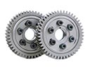 Ford F-250 Super Duty Cam Gear
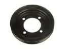 Ford F-250 Super Duty Crankshaft Pulley
 Ford F-250 Super Duty Crankshaft Seal
 Ford F-250 Super Duty Dipstick
 Ford F-250 Super Duty Engine Mount Bracket
 Ford F-250 Super Duty Engine Oil Cooler
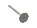 Ford F-250 Super Duty Exhaust Valve
 Ford F-250 Super Duty Harmonic Balancer
 Ford F-250 Super Duty Oil Drain Plug Gasket
 Ford F-250 Super Duty Rod Bearing
 Ford F-250 Super Duty Timing Chain
 Ford F-250 Super Duty Timing Cover Gasket