FordParts
My Garage
My Account
Cart
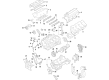
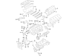
OEM Lincoln MKX Camshaft
Cam- Select Vehicle by Model
- Select Vehicle by VIN
Select Vehicle by Model
orMake
Model
Year
Select Vehicle by VIN
For the most accurate results, select vehicle by your VIN (Vehicle Identification Number).
13 Camshafts found


Lincoln MKX Camshaft, Passenger Side Part Number: 7T4Z-6250-C
$143.58 MSRP: $209.00You Save: $65.42 (32%)

Lincoln MKX Camshaft, Driver Side Part Number: 7T4Z-6250-B
$206.00 MSRP: $302.50You Save: $96.50 (32%)
Lincoln MKX Exhaust Camshaft, Passenger Side Part Number: AT4Z-6250-H
$89.35 MSRP: $137.50You Save: $48.15 (36%)
Lincoln MKX Exhaust Camshaft, Driver Side Part Number: AT4Z-6250-J
$94.81 MSRP: $138.00You Save: $43.19 (32%)Lincoln MKX Intake Camshaft, Driver Side Part Number: AT4Z-6250-G
$94.81 MSRP: $138.00You Save: $43.19 (32%)Ships in 1-3 Business Days
Lincoln MKX Intake Camshaft, Passenger Side Part Number: AT4Z-6250-F
$162.00 MSRP: $250.00You Save: $88.00 (36%)Ships in 1-3 Business Days

Lincoln MKX Camshaft Seal, Driver Side Part Number: FT4Z-6250-B
$88.51 MSRP: $128.83You Save: $40.32 (32%)Ships in 1-3 Business Days
Lincoln MKX Camshaft Seal Part Number: FT4Z-6250-J
$110.47 MSRP: $170.00You Save: $59.53 (36%)Lincoln MKX Camshaft Seal, Driver Side Part Number: FT4Z-6250-D
$80.95 MSRP: $117.83You Save: $36.88 (32%)Ships in 1-2 Business DaysLincoln MKX Camshaft Seal, Passenger Side Part Number: FT4Z-6250-C
$119.08 MSRP: $173.33You Save: $54.25 (32%)Ships in 1-3 Business Days

Lincoln MKX Camshaft, Passenger Side Part Number: 7T4Z-6250-A
Lincoln MKX Camshaft, Driver Side Part Number: 7T4Z-6250-D
$180.11 MSRP: $262.17You Save: $82.06 (32%)
Lincoln MKX Camshaft, Passenger Side Part Number: 9T4Z-6250-A
Lincoln MKX Camshaft
OEM Camshaft boasts unmatched quality. Each part goes through full quality checks. They adhere to Lincoln's official factory standards. These steps remove flaws and inconsistencies. So you can get Camshaft with long life and a perfect fit. Come to our website and find genuine Lincoln MKX parts. We keep a wide inventory of OEM MKX parts at the highly affordable prices. It's easy to search, compare, and pick what you need. You'll love the clear info and simple checkout. We offer top-rated customer service, and we reply fast. We also ship promptly to ensure your order arrives on time.
Camshaft located in Lincoln MKX vehicle helps in controlling the opening and closing of intake and exhaust valves for letting in of the air/fuel mixture and outflow of exhaust gases respectively. Dominantly made of iron or steel, the Lincoln MKX camshaft works through the following designs, Over Head Valve (OHV), Single Over Head Cam (SOHC) and Double Over Head Cam (DOHC). All these affect the engine performance uniquely, DOHC arrangement enables a precise control of both intake as well as exhaust valves. The Lincoln MKX has its camshaft driven by the crankshaft to maintain the correct timing of the valves to enhance the functioning of the engine. There exists the possibility of achieving performance variability through the intake camshafts since these are normally available in the with higher lift and longer durations that would result in increased airflow as well as power. Other important features like Lobe Separation Angle (LSA) which influences torque and idle definitely offers different driving feel in response to certain requirements.
Lincoln MKX Camshaft Parts and Q&A
- Q: How to Safely Remove and Replace a Camshaft on Lincoln MKX?A:The procedure of replacing or removing the camshaft should take place in areas with no flames or smoking because flammable mixtures possess ignition risks. Engine repairs should remain clean to prevent failed operations from foreign elements. Maintenance of the crankshaft requires free wheeling with the dowel pin set at 9 o'clock until valve clearance tests complete and both camshafts achieve installation. Turn the crankshaft to the 9 o'clock direction in a counterclockwise movement. Cleaning engine oil should cover the camshafts before installing them onto the LH and RH cylinder heads when they are positioned in the neutral position. Installation of the numbered cylinder head camshaft bearing caps requires tightness of 10 Nm (89 lb-in) for all 16 bolts distributed in a specific installation sequence. When installing fresh components the engine valve clearance needs verification by using a feeler gauge before installing new valve tappets of suitable sizes. Install the Camshaft Holding Tool at LH camshaft TDC position followed by assembling the VCT assembly with exhaust camshaft sprocket and secondary timing chain where colored links face the timing marks. Begin by applying torque to 40 Nm (30 lb-ft) then perform one complete bolt looseness and escalate torque to 10 Nm (89 lb-in) before finishing with a 90-degree bolt tightening period. The second step requires following the same installation process for the RH camshafts. Both installed camshafts need to be followed by rotating the crankshaft to 60-degree clockwise TDC position where you should place the primary timing chain with properly oriented colored links before adding the lower LH primary timing chain guide with tensioner arm that requires 10 Nm (89 lb-in) of torque. Install the primary timing chain tensioner by resetting it before positioning all timing marks correctly into place. The installation requires three bolts for each VCT housing which must be torqued to 10 Nm (89 lb-in) after ensuring that dowels completely enter the cylinder head space. The installation process requires Motorcraft High Performance Engine RTV Silicone on both engine front cover sealing surfaces and Oil Pan-to-cylinder block joint before front cover and bolt installation with 3 Nm (27 lb-in) torque setting. Begin engine front cover bracket installation by tightening specific bolts to 10 Nm (89 lb-in) then proceed to 24 Nm (18 lb-ft) for those bolts. New thread sealer must be applied to engine mount stud holes before mounting the engine studs with a torque of 20 Nm (177 lb-in). Attach the engine mount bracket and its bolts with a torque setting of 30 Nm to 22 lb-ft. The installation requires a new crankshaft front seal with tightening of the crankshaft pulley bolt across four stages. The accessory drive belt tensioner along with Power Steering Pump require installation plus any needed replacements of seals. The repair of the engine front cover-to-cylinder head joints requires RTV Silicone then the RH and LH valve covers should be fitted with new gaskets and secured with 10 Nm (89 lb-in) torque. Complete the installation of coil-on-plug assemblies which also includes wiring harness retainers and electrical connectors for the camshaft VCT solenoids with other necessary components. New to the installation process is the application of RTV Silicone at the front cover-to-cylinder head joints immediately before installing the upper Intake Manifold and support bracket bolt. Tighten this bolt to 10 Nm (89 lb-in).

Related Lincoln MKX Parts
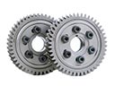 Lincoln MKX Cam Gear
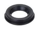 Lincoln MKX Camshaft Seal
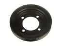 Lincoln MKX Crankshaft Pulley
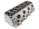 Lincoln MKX Cylinder Head
 Lincoln MKX Cylinder Head Bolts
 Lincoln MKX Dipstick
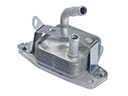 Lincoln MKX Engine Oil Cooler
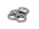 Lincoln MKX Oil Drain Plug Gasket
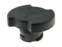 Lincoln MKX Oil Filler Cap
 Lincoln MKX Timing Belt
 Lincoln MKX Timing Chain Guide
 Lincoln MKX Valve Cover Gasket