My Garage
Cart
Make sure this part fits

Ford 5L5Z-14A664-A
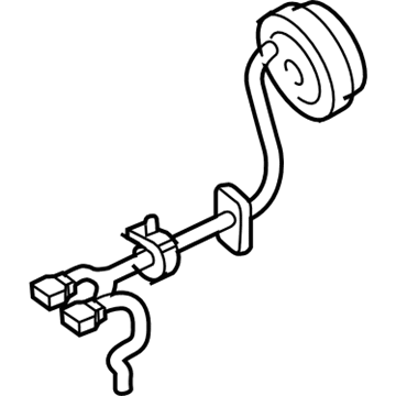
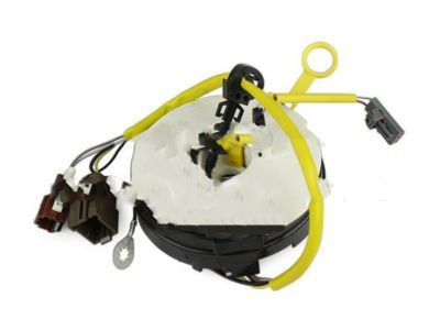
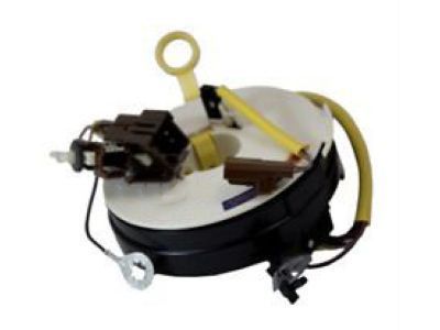
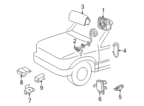
Clockspring

1998-2006 Ford 5L5Z14A664A

Customer Questions & Expert Answers (7)
Ford 5L5Z-14A664-A Clockspring
  • Part Description
    Cover And Contact Plate Assembly; Air Bag Clockspring
  • Base No.
    14A664
  • Replaces
    1L5Z-14A664-BB
  • Manufacturer
    Ford
Make sure this part fits
$94.77 MSRP: $137.95
You Save: $43.18 (32%)
Currently Unavailable

Due to manufacturer supply shortage, this item isn't currently available for ordering.

  • Related Parts
  • Product Specifications
  • Vehicle Fitment
  • Customer Questions & Expert Answers
  • Product Specifications

    BrandGenuine Ford
    Base No.14A664
    Manufacturer Part Number5L5Z-14A664-A
    Part DescriptionCover And Contact Plate Assembly; Air Bag Clockspring
    Item Dimensions8.3 x 6.1 x 3.0 inches
    Item Weight1.20 Pounds
    ConditionNew
    Fitment TypeDirect Replacement
    Replaces1L5Z-14A664-BB
    ManufacturerFord
    SKU5L5Z-14A664-A
    WarrantyThis genuine Ford part is guaranteed by Ford's factory warranty.
    Shipping & ReturnShipping Policy Return Policy
    Warning: California's Proposition 65
  • Vehicle Fitment

    Year Make Model Trim Engine
    2001 Ford ExplorerEddie Bauer, Limited, Postal, XL Fleet, XLS, XLT6 Cyl 4.0 L GAS, 8 Cyl 5.0 L GAS
    2001-2003 Ford Explorer SportBase, XLS, XLT6 Cyl 4.0 L GAS
    2001-2005 Ford Explorer Sport TracAdrenalin, Base, XL, XLS, XLT6 Cyl 4.0 L FLEX, 6 Cyl 4.0 L GAS
    1998-2006 Ford RangerEdge, FX4, Splash, Sport, STX, Tremor, XL, XLT4 Cyl 2.3 L GAS, 4 Cyl 2.5 L GAS, 6 Cyl 3.0 L FLEX, 6 Cyl 3.0 L GAS, 6 Cyl 4.0 L GAS
  • Customer Questions & Expert Answers

    Q:
    Do you think this 5L5Z-14A664-A will fit my car? Posted by FordPartsDeal Specialist
    A:
    Select Your Vehicle model to verify if part number 5L5Z-14A664-A fits your car.
    Posted by FordPartsDeal Specialist
    Q:
    How is the Clock Spring Serviced and Repaired in an Air Bag Supplemental Restraint System (SRS) on Ford Explorer Sport Trac? Posted by Customer
    A:
    When servicing or repairing Clock Spring assembly components work with safety glasses installed while servicing an air bag supplemental restraint system (SRS) vehicle and point the air bag module trim cover in a direction that does not threaten your body to prevent injuries. Depowering the system leads to the removal of two steering wheel back cover plugs and two retaining bolts for the driver air bag module so the electrical connector can get detached and the module can be taken out. Wheels need to be positioned in a straight-ahead direction before removing the steering wheel. First remove the retaining screws to place the hood release handle aside then take off the lower steering column opening finish panel along with its reinforcement. To access the upper steering column shroud one should remove the four retaining bolts that secure the steering column to instrument panel. The removal process of the tilt wheel handle shank needs to be performed when the vehicle has a steering wheel with tilting feature. Start by taking three screws off the lower steering column shroud and proceed with removing the ignition switch lock cylinder when you reach the RUN position and press the cylinder release tab to pull it outward. Take off the passive anti-theft system (PATS) transmitter after unscrewing its retaining screw and remove the key-in-ignition warning indicator switch and upper steering column shroud together with its passive anti-theft system (PATS) transmitter. The first step involves cutting the electrical connection of the Clock Spring while removing its retaining bolt to disconnect the ground wire and taking out the wire harness from its positioning points. The lower Clock Spring retaining clip must be released before removing the Clock Spring through a step of removing additional clips. When installing new Clock Springs the key must be removed before positioning the rotor at the center while preventing rotor movement. To center the rotor properly maintain the steady position of the outer housing while releasing the rotor to carefully rotate it first counterclockwise until resistance appears then clockwise three times until reaching the center position. Establish the Clock Spring on the steering column shaft and fasten the lower retaining clip while connecting all electrical connectors with pin-type retainers and ground wire bolt. The key-in-ignition warning indicator switch, PATS transmitter, along with upper and lower steering column shrouds must be installed before securing the steering column to its instrument panel retaining bolts. The wire harness should be routed into its holders. The tilt wheel handle and shank installation should be performed before fitting and adjusting the ignition switch lock cylinder into position. The installation process requires you to add the lower steering column opening finish panel reinforcement and finish panel with proper seating of retaining clips. The driver air bag module installation requires the electric connector connection followed by retaining bolt installation and finally replacement of steering wheel back cover plugs before system power activation.
    Posted by FordPartsDeal Specialist
    Q:
    What Safety Precautions and Steps Should Be Followed When Servicing the Clock Spring Assembly on Ford Ranger? Posted by Customer
    A:
    Safety glasses must be worn during Clock Spring servicing to defend against accidental air bag deployment injuries because you should handle live air bag modules by pointing their trim covers away from yourself. Serious hand washing is required to remove residual sodium hydroxide from the skin following air bag deployment. Observing the air bag module connectors will prevent system deployment and injuries so always replace discolored or damaged trim covers using new parts. Memory saver devices should never be utilized. Depowering the system begins with removing the driver air bag module after setting the wheels to face directly ahead of the vehicle. Use proper tools to detach the hood release handle together with the steering column opening finish panel and its reinforcement by removing the required screws and bolts. To access the Clock Spring retaining clips workers need to first remove the tilt wheel handle along with the lower steering column shroud. The process requires disconnecting the Clock Spring wire harness alongside its electrical connectors before releasing the retaining clips to remove the Clock Spring. Install the new Clock Spring at the center by first removing the key from the ignition while holding the steering wheel rotor. Start by securing the outer housing while letting go of the rotor to perform counterclockwise rotation until resistance comes up and perform clockwise rotation amounting to 2.25 turns to attain the center position. Mount the Clock Spring on its steering column position and use authority to secure the retaining tabs. Safety procedures should begin with reattaching the key-in-ignition warning indicator switch and lower retaining clip as well as electrical connectors while confirming securement of pin-type retainers. Return the steering column shrouds to position while installing the tilt wheel handle and finishing the panel components by tightening bolts to 12 Nm (9 lb-ft). The final step requires installation of both steering wheel and driver air bag module prior to restarting the system power.
    Posted by FordPartsDeal Specialist
    Q:
    What is the purpose of the restraint system diagnostic tool for the 2001 Ford Explorer? Posted by Customer
    A:
    It is for service only and must be removed from the vehicle before road use to avoid injury and potential violation of vehicle safety standards.
    Posted by FordPartsDeal Specialist
    See expert answers on similar Clock Spring
    Q:
    What components need to be removed to access the driver airbag module for the 2005 Ford Explorer Sport Trac? Posted by Customer
    A:
    Remove the two steering wheel back cover plugs and the two retaining bolts for the driver air bag module, then disconnect the electrical connector and remove the module.
    Posted by FordPartsDeal Specialist
    See expert answers on similar Clock Spring
    Q:
    What should be ensured before removing the steering wheel for the 2004 Ford Ranger? Posted by Customer
    A:
    Ensure the wheels are straight ahead.
    Posted by FordPartsDeal Specialist
    See expert answers on similar Clock Spring
    Q:
    What should be done if using a new clockspring for the 2005 Ford Ranger? Posted by Customer
    A:
    Remove the key while holding the rotor in a centralized position, ensuring it does not turn.
    Posted by FordPartsDeal Specialist
    See expert answers on similar Clock Spring
    If you have any questions about this product, please don't hesitate to ask us. We will be happy to help you!

OEM Ford 5L5Z-14A664-A, Excellent Performance and Perfect Fitment

To ensure reliability, purchase Ford part # 5L5Z-14A664-A Clockspring. It is sometimes referred to as Ford Clock Spring. For those Ford owners who aspire to maintain their vehicles in optimal shape, opting for OEM parts is a wise choice. Precisely engineered, these components adhere to stringent factory guidelines and are produced in state-of-the-art facilities using cutting-edge technologies. Moreover, they are subjected to thorough testing to certify their resilience and safety, thereby making them a dependable option for Ford owners.

FordPartsDeal.com is a leading supplier of genuine Ford parts such as Ford 5L5Z14A664A Clockspring. A vast selection of genuine Ford parts is available on our website, all offered at discounted prices. Every OEM Ford part is covered by the manufacturer's warranty, which also applies to our hassle-free return policy. Enjoy fast delivery service, ensuring you get your parts when you need them. Your shopping experience here is guaranteed to be pleasurable. For detailed Ford parts information, click here.
Choose FordPartsDeal for discounted prices, exceptional service and fast delivery