
Popular OEM Ford Explorer Parts
- Body & Hardware Parts View More >
- Electrical Parts View More >
- Interior & Exterior Trim Parts View More >
- Air & Fuel Delivery Parts View More >
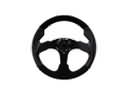
- Steering Parts View More >
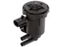
- Emission Control & Exhaust Parts View More >
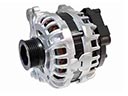
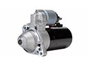
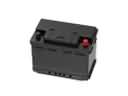
- Charging & Starting Parts View More >
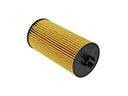
- Engine Parts View More >
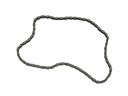
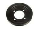
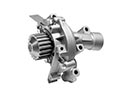
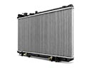
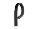
- Belts & Cooling Parts View More >
- Suspension Parts View More >
- Brakes Parts View More >
- A/C & Heating Parts View More >


Why Buy Genuine Ford Explorer Parts From FordPartsDeal.com
FordPartsDeal.com offers a smart and convenient way to buy genuine parts online. We sell new OEM Ford Explorer parts, including Headlights & Lighting. Authorized dealers directly provide all the Ford Explorer parts and assemblies to ensure the optimal quality and fit. We also provide all properly fitting Ford Explorer parts, such as Transmission, Driveline & Axles specific to your model. When you shop here, you get real Ford value at highly competitive prices. All our products come with the same Ford warranty available at other dealerships. Our easy-to-use catalog helps you quickly identify the right part for your car. You'll receive fast shipping from our warehouse network, keeping your Ford Explorer running smoothly. Our staff consists of Ford professionals who are ready to assist you. We aim to treat each customer as if they were stepping out of a Ford showroom. VIN verification and our live support ensure that the part you order is the right Ford Explorer part for your vehicle.
The Ford Explorer took over from the two-door Bronco II by entering the market in 1990 to focus on family-oriented four-door SUVs. The Explorer's engineering platform draws power from the Ford Ranger chassis design to provide solid durability components united with top-tier operational capabilities. RWD served as the base configuration for the first-generation Ford Explorer yet customers had the optional AWD system using a Borg-Warner transfer case that enhanced grip under diverse conditions. The powertrain selection has progressed throughout different Explorer generations to achieve improved effectiveness and greater capability. Between 1995 and 2001 the second-generation Ford Explorer integrated enhanced braking systems with disc brakes and it received an advanced four-wheel-drive (4WD) system which delivered better maneuvering potential. Black B- and D-pillars distinguish the Ford Explorer design because they were added as custom features during its production. Different Ford Explorer trim levels arrived on the market with the XLS as the base version followed by the XLT and Eddie Bauer models created to satisfy diverse customer needs. The use of genuine Ford components for Explorer vehicles makes perfect sense because it delivers peak performance and extended longevity alongside exact vehicle fit specifications for safe multiyear operation.
Ford Explorer issues group into air conditioning, steering hydraulics, and intake sealing. In the air conditioning system, leaking O-rings or a cracked AC condenser cause refrigerant loss. The Explorer may blow warm air and leave oil stains at coupling joints. Use fluorescent dye, inspect under the radiator support, and replace the AC condenser or seals on the Explorer. In steering hydraulics, old fluid contaminates the power steering pump and gearbox. The Ford Explorer can growl while turning and display heavy effort at parking speeds. Flush the system, verify flow, and replace the power steering pump on the Explorer if noisy. For engine performance, intake leaks at the intake manifold gasket create unmetered air. The Ford Explorer may idle rough, misfire, or stall, with a stored lean code. Smoke test, inspect vacuum lines, and install a new intake manifold gasket to restore trims. Finish with a road test so the Ford Explorer runs cool, steers quietly, and accelerates cleanly. Verify AC pressure with gauges, evacuate, and recharge to factory weight after sealing repairs. Bleed the steering system, then recheck for metal, noise, and assist stability after service.
Ford Explorer Parts and Q&A
- Q: How to Service and Repair the Water Pump for the 4.0L SOHC Engine on Ford Explorer?A:Service the coolant pump with the 4.0L SOHC engine, drain cooling system, loosen cooling fan and accessory drive belt, and disconnect hoses. Take out the coolant pump, gasket without using metal tools to clean it. Lastly, repeat the process by opening the package and replacing the old coolant pump and gasket with the new one.
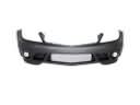
- Q: How to remove and replace the front bumper cover on Ford Explorer?A:Remove headlamp assemblies. Disconnect fog and side-turn signal connectors. Remove splash-shield screws/retainers and shields, then two lower bumper-cover bolts. Explorer/Sport Trac: remove six grille-panel scrivets and release locking tabs. Release cover-to-fender clips; Mountaineer: remove upper screws. Rotate, press to release three tabs; remove cover; reinstall reverse.
- Q: How to service and repair the alternator on Ford Explorer?A:To maintain the alternator when it is necessary, unconnecting the battery, rotate the belt tensioner, and take off the belt. Unscrew the protective cover, unscrew the generator B+ terminal and connector and remove the generator bolts. The process is reversed and all components placed with correct torque requirements.


