FordParts
My Garage
My Account
Cart
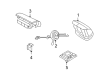
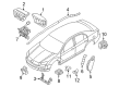
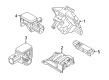
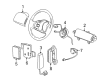
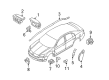
OEM Ford Clock Spring
Spiral Cable Clock Spring- Select Vehicle by Model
- Select Vehicle by VIN
Select Vehicle by Model
orMake
Model
Year
Select Vehicle by VIN
For the most accurate results, select vehicle by your VIN (Vehicle Identification Number).
145 Clock Springs found


Ford Clockspring Part Number: AC2Z-14A664-C
$116.98 MSRP: $170.28You Save: $53.30 (32%)Product Specifications- Other Name: Cover And Contact Plate Assembly; Air Bag Clockspring


Ford Clockspring Part Number: 4C2Z-14A664-BA
$98.81 MSRP: $143.83You Save: $45.02 (32%)Ships in 1-2 Business DaysProduct Specifications- Other Name: Cover And Contact Plate Assembly; Air Bag Clockspring
- Manufacturer Note: Less speed control


Ford Clockspring Part Number: 6R3Z-14A664-AA
$111.11 MSRP: $161.73You Save: $50.62 (32%)Ships in 1-2 Business DaysProduct Specifications- Other Name: Cover And Contact Plate Assembly; Air Bag Clockspring
- Replaces: 4R3Z-14A664-AA

Ford Clockspring Part Number: AC2Z-14A664-A
$118.86 MSRP: $182.92You Save: $64.06 (36%)Product Specifications- Other Name: Cover And Contact Plate Assembly; Air Bag Clockspring


Ford Clockspring Part Number: 8L8Z-14A664-A
$130.13 MSRP: $200.82You Save: $70.69 (36%)Ships in 1-3 Business DaysProduct Specifications- Other Name: Cover And Contact Plate Assembly; Air Bag Clockspring


Ford Clockspring Part Number: 7S4Z-14A664-A
$140.44 MSRP: $216.73You Save: $76.29 (36%)Ships in 1-3 Business DaysProduct Specifications- Other Name: Cover And Contact Plate Assembly; Air Bag Clockspring
- Replaces: 4S4Z-14A664-AA


Ford Clockspring Part Number: D2BZ-14A664-A
$158.83 MSRP: $231.20You Save: $72.37 (32%)Ships in 1-2 Business DaysProduct Specifications- Other Name: Cover And Contact Plate Assembly; Air Bag Clockspring
- Replaces: BE8Z-14A664-A


Ford Clockspring Part Number: DV6Z-14A664-A
$165.10 MSRP: $240.32You Save: $75.22 (32%)Ships in 1-2 Business DaysProduct Specifications- Other Name: Cover And Contact Plate Assembly; Air Bag Clockspring


Ford Clockspring Part Number: 8C2Z-14A664-A
$92.04 MSRP: $133.97You Save: $41.93 (32%)Ships in 1-3 Business DaysProduct Specifications- Other Name: Cover And Contact Plate Assembly; Air Bag Clockspring


Ford Clockspring Part Number: 4C2Z-14A664-AA
$94.66 MSRP: $137.78You Save: $43.12 (32%)Ships in 1 Business DayProduct Specifications- Other Name: Cover And Contact Plate Assembly; Air Bag Clockspring
- Manufacturer Note: W/SPEED CONTROL

Ford Clockspring Part Number: F8UZ-14A664-DA
$97.10 MSRP: $141.33You Save: $44.23 (32%)Ships in 1-2 Business DaysProduct Specifications- Other Name: Cover And Contact Plate Assembly; Air Bag Clockspring


Ford Clockspring Part Number: 6W1Z-14A664-A
$97.91 MSRP: $142.52You Save: $44.61 (32%)Product Specifications- Other Name: Cover And Contact Plate Assembly; Air Bag Clockspring
- Manufacturer Note: AFTER 05/23/06
- Replaces: 5W1Z-14A664-AA


Ford Clockspring Part Number: 8C2Z-14A664-B
$97.28 MSRP: $141.60You Save: $44.32 (32%)Ships in 1 Business DayProduct Specifications- Other Name: Cover And Contact Plate Assembly; Air Bag Clockspring


Ford Clockspring Part Number: BE5Z-14A664-A
$100.08 MSRP: $145.68You Save: $45.60 (32%)Product Specifications- Other Name: Cover And Contact Plate Assembly; Air Bag Clockspring
- Replaces: 6E5Z-14A664-B, 8E5Z-14A664-A


Ford Clockspring Part Number: 3M5Z-14A664-B
$100.99 MSRP: $147.00You Save: $46.01 (32%)Ships in 1-3 Business DaysProduct Specifications- Other Name: Cover And Contact Plate Assembly; Air Bag Clockspring
- Replaces: 3M5Z-14A664-A

Ford Clockspring Part Number: F7UZ-14A664-EC
$103.06 MSRP: $150.02You Save: $46.96 (32%)Ships in 1-3 Business DaysProduct Specifications- Other Name: Cover And Contact Plate Assembly; Air Bag Clockspring
- Manufacturer Note: Less speed control


Ford Clockspring Part Number: F85Z-14A664-AA
$98.00 MSRP: $150.82You Save: $52.82 (36%)Product Specifications- Other Name: Cover And Contact Plate Assembly; Air Bag Clockspring
- Replaces: F75Z-14A664-FE


Ford Clockspring Part Number: BE5Z-14A664-B
$105.15 MSRP: $153.05You Save: $47.90 (32%)Product Specifications- Other Name: Cover And Contact Plate Assembly; Air Bag Clockspring
- Replaces: 9E5Z-14A664-A


Ford Clockspring Part Number: 8G1Z-14A664-A
$108.95 MSRP: $158.58You Save: $49.63 (32%)Product Specifications- Other Name: Cover And Contact Plate Assembly; Air Bag Clockspring


Ford Clockspring Part Number: 1R3Z-14A664-AA
$118.83 MSRP: $172.97You Save: $54.14 (32%)Ships in 1-3 Business DaysProduct Specifications- Other Name: Cover And Contact Plate Assembly; Air Bag Clockspring
- Replaces: XR3Z-14A664-AA
| Page 1 of 8 |Next >
1-20 of 145 Results
Ford Clock Spring
If you own Ford and want to keep it in top shape, choosing OEM Clock Spring is a smart move. They are precisely engineered and follow strict factory standards. They are made in advanced facilities that use cutting edge technology. Each part goes through thorough testing to confirm strength and safety, so you can trust it. FordPartsDeal.com gives you genuine Ford Clock Spring at some of the affordable online prices without cutting quality. Every OEM Ford part includes the manufacturer's warranty, easy returns, and super-fast delivery. So why wait? Shop now and get your vehicle back to peak condition.
Ford Clock Spring maintains airbag wires in the running state and the steering wheel can rotate freely. In 1913, Ford was the first to invent the moving assembly line, reducing construction time, reducing cost, and enabling ordinary families to leap off horse carts into personal vehicles. Ford is aggressive with EcoBoost turbo engines that are larger than they look and have a highway mileage that belonged to small compacts. Ford integrates SYNC voice control to the extent where drivers scream a song title, directions, or a text without pressing a single button. Ford supports safety Co-Pilot360, which is a layer of automatic braking, blind-spot notification, and lane keeping nudges to protect every journey. Electric models such as the F-150 Lightning demonstrate that powerful trucks can run silently, pull heavy loads, and pass by gas stations without any effort. Clock Spring is curled into the steering hub and is a flat multicore ribbon that is wound tight enough to contain flex, which does not weaken in the face of untold rotations. Clock Spring connects wheel buttons, horn, and airbag squib to the main harness of the vehicle and ensures that all circuits remain live with full rotation of the lock. Clock Spring battling strips are cut through reinforced polymers and finer track finishes, which remove friction that would be applied to scrape conductors and spike resistance. Clock Spring can be changed within minutes using simple equipment and clear signals are restored so airbags can deploy when a millisecond counts.
Ford Clock Spring Parts and Q&A
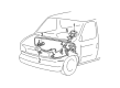
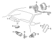
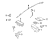
- Q: What Precautions and Steps Are Involved in Servicing the Clock Spring Assembly on Ford Mustang?A:Green safety glasses become essential for servicing Clock Spring assemblies since they reduce potential air bag injuries along with the elimination of memory saver devices during this procedure. A warning light from the air bag system will appear due to removing the RCM fuse while the ignition switch remains ON but this condition does not represent a faulty sensor system. SRS operation needs to be completely functional and faultless to send the vehicle back to customers, repairing it requires new equipment installation unless the problem remains where you should reinstall the original piece and run diagnostics again. Start by disabling power to the system then position the road wheels directly forward. Lower the steering wheel till it reaches its lowest position while securing the tilt handle then take out the driver air bag module and steering wheel. As the following step unpack the two screws that fasten both the lower steering column shroud and the upper steering column shroud. The Clock Spring will be reusable only if you tape the rotor center to the housing outer to stop rotation. Use care when releasing the tilt handle while you move the spring-loaded tilt steering column then position the bottom steering column shroud downward. You will first disable the Clock Spring electrical connector before proceeding to remove its four screws to extract the Clock Spring component. To recenter the Clock Spring of some vehicles maintain the outer housing position while turning the rotor counterclockwise until resistance occurs and continuing clockwise rotation for three more turns until ribbon wire visibility shows across the window along with rotor arrow alignment into housing arrow position. Through four screws secure the Clock Spring before attaching the electrical connector and finally place the lower steering column shroud in its correct position. Take your time while lowering the steering column and activate the tilting lock. When retaining the Clock Spring users should detach the tape while steering wheel maintenance is in progress. Follow the procedure to center the Clock Spring and avoid rotating it before steering wheel installation; neglecting this step requires a new centering sequence. Fasten the upper steering column shroud first followed by both screws that secure the lower shroud before adding the steering wheel. As a final step in the procedure you need to install the driver air bag module before powering up the system.
- Q: What Safety Precautions and Steps Should Be Followed When Servicing the Clock Spring Assembly on Ford Ranger?A:Safety glasses must be worn during Clock Spring servicing to defend against accidental air bag deployment injuries because you should handle live air bag modules by pointing their trim covers away from yourself. Serious hand washing is required to remove residual sodium hydroxide from the skin following air bag deployment. Observing the air bag module connectors will prevent system deployment and injuries so always replace discolored or damaged trim covers using new parts. Memory saver devices should never be utilized. Depowering the system begins with removing the driver air bag module after setting the wheels to face directly ahead of the vehicle. Use proper tools to detach the hood release handle together with the steering column opening finish panel and its reinforcement by removing the required screws and bolts. To access the Clock Spring retaining clips workers need to first remove the tilt wheel handle along with the lower steering column shroud. The process requires disconnecting the Clock Spring wire harness alongside its electrical connectors before releasing the retaining clips to remove the Clock Spring. Install the new Clock Spring at the center by first removing the key from the ignition while holding the steering wheel rotor. Start by securing the outer housing while letting go of the rotor to perform counterclockwise rotation until resistance comes up and perform clockwise rotation amounting to 2.25 turns to attain the center position. Mount the Clock Spring on its steering column position and use authority to secure the retaining tabs. Safety procedures should begin with reattaching the key-in-ignition warning indicator switch and lower retaining clip as well as electrical connectors while confirming securement of pin-type retainers. Return the steering column shrouds to position while installing the tilt wheel handle and finishing the panel components by tightening bolts to 12 Nm (9 lb-ft). The final step requires installation of both steering wheel and driver air bag module prior to restarting the system power.


Related Ford Parts
 Ford Ignition Coil
 Ford Ignition Switch
 Ford MAP Sensor
 Ford Instrument Cluster
 Ford Neutral Safety Switch
 Ford Coolant Temperature Sensor
 Ford Speedometer
 Ford Flasher Relay
 Ford Mirror Switch
 Ford Power Window Switch
 Ford Air Bag Sensor
 Ford Temperature Sender
Browse Ford Clock Spring by Models
Ranger Bronco Mustang Explorer Focus Fusion F-150 Maverick Escape Edge Excursion Expedition Fiesta Taurus Thunderbird Flex Transit Connect Bronco Sport Explorer Sport Trac Crown Victoria EcoSport Escort F-250 Aerostar C-Max Contour E-150 Econoline Explorer Sport F-350 Five Hundred Freestar Freestyle Mustang Mach-E Police Interceptor Utility Taurus X Windstar F-350 Super Duty Police Interceptor Sedan E-150 E-150 Club Wagon E-150 Econoline Club Wagon E-250 E-250 Econoline E-350 Club Wagon E-350 Econoline E-350 Econoline Club Wagon E-350 Super Duty E-Transit F-150 Heritage F-150 Lightning F-250 HD F-250 Super Duty Police Responder Hybrid Special Service Police Sedan SSV Plug-In Hybrid Transit-150 Transit-250 Transit-350 Transit-350 HD