FordParts
My Garage
My Account
Cart
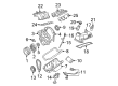
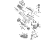
OEM 2001 Ford Explorer Intake Manifold
Engine Intake Manifold- Select Vehicle by Model
- Select Vehicle by VIN
Select Vehicle by Model
orMake
Model
Year
Select Vehicle by VIN
For the most accurate results, select vehicle by your VIN (Vehicle Identification Number).
4 Intake Manifolds found


2001 Ford Explorer Intake Manifold Part Number: 4L5Z-9424-A
$377.96 MSRP: $555.00You Save: $177.04 (32%)Product Specifications- Other Name: Kit - Manifold Hardware; Engine Intake Manifold
- Replaces: 1L5Z-9424-DA, 4L5Z-9424-BA
- Base No.: 9424
- Item Weight: 12.50 Pounds
- Item Dimensions: 23.8 x 12.5 x 11.5 inches
- Condition: New
- Fitment Type: Direct Replacement
- SKU: 4L5Z-9424-A
- Warranty: This genuine part is guaranteed by Ford's factory warranty.

2001 Ford Explorer Intake Manifold Part Number: YL2Z-9424-AA
Product Specifications- Other Name: Manifold Assembly - Inlet; Manifold
- Base No.: 9424
- Item Weight: 1.40 Pounds
- Item Dimensions: 15.7 x 8.1 x 4.7 inches
- Condition: New
- Fitment Type: Direct Replacement
- SKU: YL2Z-9424-AA
- Warranty: This genuine part is guaranteed by Ford's factory warranty.
2001 Ford Explorer Intake Manifold Part Number: XL2Z-9424-CA
Product Specifications- Other Name: Manifold Assembly - Inlet; Manifold
- Manufacturer Note: Upper. Includes 9E926 Throttle Body. Includes mounting screws W705464-S309., SOHC
- Base No.: 9424
- Item Weight: 9.40 Pounds
- Item Dimensions: 19.9 x 7.1 x 12.8 inches
- Condition: New
- Fitment Type: Direct Replacement
- SKU: XL2Z-9424-CA
- Warranty: This genuine part is guaranteed by Ford's factory warranty.
2001 Ford Explorer Intake Manifold, Upper Part Number: XL2Z-9424-BA
Product Specifications- Other Name: Manifold Assembly - Inlet; Manifold
- Manufacturer Note: Upper - Includes 9J459 EGR Control & 9J460 Sensor, For external type EGR
- Position: Upper
- Base No.: 9424
- Item Dimensions: 19.1 x 12.7 x 10.3 inches
- Condition: New
- Fitment Type: Direct Replacement
- SKU: XL2Z-9424-BA
- Warranty: This genuine part is guaranteed by Ford's factory warranty.
2001 Ford Explorer Intake Manifold
If you're seeking quality and affordability, look no further than our extensive inventory of genuine 2001 Ford Explorer Intake Manifold available at FordPartsDeal.com. You can confidently purchase our OEM 2001 Ford Explorer Intake Manifold as they are supported by the manufacturer's warranty and our hassle-free return policy, alongside the benefit of our fast delivery service.
2001 Ford Explorer Intake Manifold Parts Q&A
- Q: How to Service and Repair an Intake Manifold on 2001 Ford Explorer?A: Service and repairs of the upper intake manifold begin by disconnecting the battery cable from the ground then removing the air cleaner outlet tube. First disconnect the idle air control (IAC) electrical connector before you remove the bolt securing the accelerator control splash shield and forward position (TP) sensor electrical connector. Service of the upper intake manifold begins by disassembling the throttle linkage through accelerator speed control cable removal followed by acceleration cable bracket bolt and lower cable bracket nut removal then finally separating cables from clips and accelerator bracket. Separate the lines which enable vacuum flow to the EGR valve and the fuel pressure regulator and the upper EGR tube from exhaust manifold respectively. Detach the engine vacuum regulator (EVR) electrical connector and vacuum connector while also disconnecting the EGR backpressure transducer electrical connector then remove the ignition coil bracket. First disconnect the accelerator cable from upper intake manifold clips. Then remove screws underneath the intake cover plate and finally proceed with removing the specified bolts in sequence. Connectors from the front of the intake manifold and the vapor management valve (VMV) purge line and the brake booster vacuum supply line to the LH rear upper intake connection should be disconnected together with the positive crankcase ventilation (PCV) hose and the two PCV heater hoses. Detach and dispose of the upper intake manifold followed by removal of the worn gasket. The installation requires cleaning the surfaces of both upper and lower intake manifold gaskets through the use of Metal Surface Cleaner F4AZ-19A536-RA or an equivalent cleanser. All surfaces must be checked for cleanliness before using new seals and gaskets. Install the upper intake manifold with its gasket then bolt all fixings while attaching the PCV tube along with both upper intake vacuum connections and the two PCV heater hoses. After hooking up the vacuum supply line to the brake booster properly tighten the specified bolts then place the upper intake manifold cover plate and fasten the screws. First install the accelerator cable bracket while subsequently tightening the lower accelerator cable bracket nut and then installing the accelerator cable bracket nut. Connect both throttle linkage cables from the accelerator and speed control devices and place them into their designated clip before installing the ignition coils and their bracket. In the performance of this remedy, regain electrical connectivity between the EVR electrical connector, EVR vacuum connector, EGR valve vacuum connector, fuel pressure regulator vacuum connector, upper EGR valve-to-exhaust manifold tube connection, and EGR backpressure transducer electrical connection. After connecting the electrical connectors of the TP sensor and IAC the technician should install the splash shield and outlet tube while also reattaching the electrical ground.
Related 2001 Ford Explorer Parts
 2001 Ford Explorer Fuel Pump
 2001 Ford Explorer Throttle Body
 2001 Ford Explorer Fuel Filter
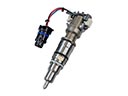 2001 Ford Explorer Fuel Injector
 2001 Ford Explorer Fuel Tank
 2001 Ford Explorer Intake Manifold Gasket
 2001 Ford Explorer Mass Air Flow Sensor
 2001 Ford Explorer Air Filter Box
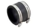 2001 Ford Explorer Air Intake Coupling
 2001 Ford Explorer Fuel Filler Neck
 2001 Ford Explorer Fuel Tank Strap
 2001 Ford Explorer Throttle Body Gasket