FordParts
My Garage
My Account
Cart
OEM 2001 Mercury Grand Marquis Fuel Rail
Engine Fuel Rail- Select Vehicle by Model
- Select Vehicle by VIN
Select Vehicle by Model
orMake
Model
Year
Select Vehicle by VIN
For the most accurate results, select vehicle by your VIN (Vehicle Identification Number).
1 Fuel Rail found


2001 Mercury Grand Marquis Fuel Rail Part Number: 1W7Z-9F792-AA
Product Specifications- Other Name: Manifold Assembly - Fuel; Manifold Assembly - Fuel Supply
- Base No.: 9F792
- Item Weight: 1.00 Pounds
- Condition: New
- Fitment Type: Direct Replacement
- SKU: 1W7Z-9F792-AA
- Warranty: This genuine part is guaranteed by Ford's factory warranty.
2001 Mercury Grand Marquis Fuel Rail
If you're seeking quality and affordability, look no further than our extensive inventory of genuine 2001 Mercury Grand Marquis Fuel Rail available at FordPartsDeal.com. You can confidently purchase our OEM 2001 Mercury Grand Marquis Fuel Rail as they are supported by the manufacturer's warranty and our hassle-free return policy, alongside the benefit of our fast delivery service.
2001 Mercury Grand Marquis Fuel Rail Parts Q&A
- Q: How to service the fuel rail safely and effectively on 2001 Mercury Grand Marquis?A: In order to service the fuel rail, be safe by preventing flames, disconnecting the battery, and relieving pressure. Take away required parts, such as throttle body, and EGR valve. Unscrew wiring and connectors and take out the fuel injection manifold. To install, lubricate O-rings, reconnect components, and so forth, and fasten everything in place before reassembling the battery.
Related 2001 Mercury Grand Marquis Parts
 2001 Mercury Grand Marquis Fuel Pump
 2001 Mercury Grand Marquis Fuel Tank
 2001 Mercury Grand Marquis Air Duct
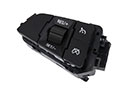 2001 Mercury Grand Marquis Cruise Control Switch
 2001 Mercury Grand Marquis Fuel Filler Neck
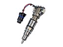 2001 Mercury Grand Marquis Fuel Injector
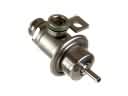 2001 Mercury Grand Marquis Fuel Pressure Regulator
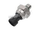 2001 Mercury Grand Marquis Fuel Pressure Sensor
 2001 Mercury Grand Marquis Fuel Tank Sending Unit
 2001 Mercury Grand Marquis Fuel Tank Strap
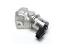 2001 Mercury Grand Marquis Idle Control Valve
 2001 Mercury Grand Marquis Mass Air Flow Sensor