FordParts
My Garage
My Account
Cart
OEM 2002 Mercury Villager Clock Spring
Spiral Cable Clock Spring- Select Vehicle by Model
- Select Vehicle by VIN
Select Vehicle by Model
orMake
Model
Year
Select Vehicle by VIN
For the most accurate results, select vehicle by your VIN (Vehicle Identification Number).
1 Clock Spring found

2002 Mercury Villager Clockspring Part Number: XF5Z-14A664-BA
Product Specifications- Other Name: Cover And Contact Plate; Air Bag Clockspring; Cover And Contact Plate Assembly
- Manufacturer Note: Kit: includes contact,att. parts IS sheet
- Replaces: XF5Z-14A664-AB
- Item Weight: 0.30 Pounds
- Condition: New
- Fitment Type: Direct Replacement
- SKU: XF5Z-14A664-BA
- Warranty: This genuine part is guaranteed by Ford's factory warranty.
2002 Mercury Villager Clock Spring
If you're seeking quality and affordability, look no further than our extensive inventory of genuine 2002 Mercury Villager Clock Spring available at FordPartsDeal.com. You can confidently purchase our OEM 2002 Mercury Villager Clock Spring as they are supported by the manufacturer's warranty and our hassle-free return policy, alongside the benefit of our fast delivery service.
2002 Mercury Villager Clock Spring Parts Q&A
- Q: What Precautions Should Be Taken When Servicing the Clock Spring on 2002 Mercury Villager?A: Wear safety glasses and dislodge the air bag module when servicing it so that it does not hurt you. Always disconnect the battery prior to starting, as well as special steps in removing components. Install the Clock Spring by centering the spring and avoiding failure and subsequent installation of the SRS by reversing the procedure.
Related 2002 Mercury Villager Parts
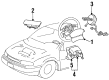
 2002 Mercury Villager Air Bag
 2002 Mercury Villager Air Bag Sensor
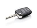 2002 Mercury Villager Car Key
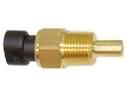 2002 Mercury Villager Coolant Temperature Sensor
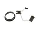 2002 Mercury Villager Fuel Level Sensor
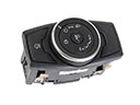 2002 Mercury Villager Headlight Switch
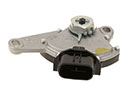 2002 Mercury Villager Neutral Safety Switch
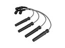 2002 Mercury Villager Spark Plug Wire
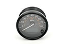 2002 Mercury Villager Speedometer
 2002 Mercury Villager Temperature Sender
 2002 Mercury Villager Transmitter
 2002 Mercury Villager Window Switch