FordParts
My Garage
My Account
Cart
OEM 2005 Ford Explorer Brake Pedal
Brake Pedal Pad- Select Vehicle by Model
- Select Vehicle by VIN
Select Vehicle by Model
orMake
Model
Year
Select Vehicle by VIN
For the most accurate results, select vehicle by your VIN (Vehicle Identification Number).
2 Brake Pedals found

2005 Ford Explorer Pedal Assembly Part Number: 3L2Z-2455-AA
Product Specifications- Other Name: Pedal Assembly - Brake; Brake Pedal Assembly; Adjuster
- Base No.: 2455A
- Item Weight: 5.10 Pounds
- Condition: New
- Fitment Type: Direct Replacement
- SKU: 3L2Z-2455-AA
- Warranty: This genuine part is guaranteed by Ford's factory warranty.

2005 Ford Explorer Pedal Assembly Part Number: 1L2Z-2455-BA
Product Specifications- Other Name: Pedal Assembly - Brake; Brake Pedal Assembly
- Base No.: 2455B
- Item Weight: 10.70 Pounds
- Condition: New
- Fitment Type: Direct Replacement
- SKU: 1L2Z-2455-BA
- Warranty: This genuine part is guaranteed by Ford's factory warranty.
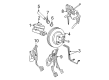
2005 Ford Explorer Brake Pedal
If you're seeking quality and affordability, look no further than our extensive inventory of genuine 2005 Ford Explorer Brake Pedal available at FordPartsDeal.com. You can confidently purchase our OEM 2005 Ford Explorer Brake Pedal as they are supported by the manufacturer's warranty and our hassle-free return policy, alongside the benefit of our fast delivery service.
2005 Ford Explorer Brake Pedal Parts Q&A
- Q: How to service and repair the brake pedal assembly on 2005 Ford Explorer?A: Service and repair of the brake pedal assembly needs adjustable pedals in full forward position access while Supplemental Restraint System (SRS) should be depowered first. Before detaching the speed control deactivator switch it is fundamental to maintain the brake pedal connected to the booster rod when it is at rest to avoid damage to the system. Proceed by removing the speed control deactivator switch then unfasten both the booster rod redundant self-locking pin cover and self-locking pin. The brake pedal requires removal of stoplamp switch bushing and spacers and brake booster rod until the stoplamp switch is set aside. Power adjustable pedal vehicles require disconnecting the adjustable pedal motor electrical connector together with the accelerator pedal motor electrical connector. Inspection of the brake booster assembly requires removal of its four attaching nuts to move it and the brake master cylinder assembly forward from the mounting studs. Start by taking off the brake pedal bracket nuts together with the two wiper arms and unfastening the cowl grille using its 14 spring clips. Start by removing both instrument panel support bracket bolts and two nuts and procedures with the front floor console followed by the four instrument panel support bracket bolts from each of the left-hand and right-hand instrument support brackets. Begin by taking off the two door scuff plates then the retainer followed by removal of the two A-pillar lower trim panels and then the two instrument panel side finish panels after which you must remove the four A-pillar passenger assist handle caps and their respective four bolts before advancing to the next part of the procedure. Proceed to remove first the two windshield side garnish mouldings together with the defroster grille and duct bolt and the top instrument panel to cowl bolt. Secure the steering wheel when removing the two steering column opening cover screws because rotational movement of the steering column intermediate shaft could harm the Clock Spring. First disconnect the bulkhead electrical connectors after removing the bolt from the steering intermediate shaft pinch and separating the two steering shafts. Reduce the distance between the instrument panel and dash panel to 25.4 mm (1 inch) after you remove the four instrument panel to cowl support bolts. Then you can uninstall the brake pedal assembly from the vehicle. Placing the brake pedal assembly inside the vehicle first followed by setting up the instrument panel and installing four instrument panel to cowl support bolts which need tightening up to 25 Nm (18 ft. lbs.). First secure the steering shafts before installing the pinch bolt and tightening it to 30 Nm (22 ft. lbs.). After this attach the bulkhead electrical connectors and fasten the corresponding bolt. The first step involves installing the steering column opening cover and its two screws then installing the instrument panel duct support bolt followed by the instrument panel to cowl support bolt which requires torquing to 9 Nm (80 inch lbs.) and 30 Nm (22 ft. lbs.). To complete this step secure the defroster grille and two windshield side garnish mouldings by inserting four bolts which must be tightened up to 11Nm (8 ft. lbs.). Then add and fasten the two A-pillar passenger assist handles that require bolts secured with 11 Nm (8 ft. lbs.) torque. Position the four A-pillar passenger assist handle caps followed by the two instrument panel side finish panels and the two A-pillar lower trim panels with retainers and the two door scuff plates. The left-hand and right-hand instrument support brackets receive four instrument panel support bracket bolts before tightening the instrument panel support bolt to 30 Nm (22 ft. lbs.). Reinstall the front floor console and the two wiper arms along with the cowl grille. Place the brake master cylinder and brake booster assembly in the brake pedal bracket assembly before tightening all three brake pedal bracket nuts to 7 Nm (62 inch lbs.). Use four new brake booster nuts before you securely torque each of them to reach 22 Nm (16 ft. lbs.). The vehicle requires a connection of adjustable pedal motor electrical connector and accelerator pedal electrical connector if power adjustable pedals are installed. Position the stoplamp switch, bushing and spacers on the brake pedal before adding the redundant self-locking pin and its cover. The brake pedal should be joined with the brake booster rod at rest before speed control deactivator switch installation to prevent damage while you should power up the Supplementary Restraint System next.
Related 2005 Ford Explorer Parts
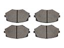 2005 Ford Explorer Brake Pads
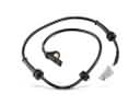 2005 Ford Explorer ABS Sensor
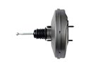 2005 Ford Explorer Brake Booster
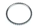 2005 Ford Explorer ABS Reluctor Ring
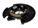 2005 Ford Explorer Brake Backing Plate
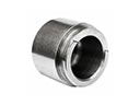 2005 Ford Explorer Brake Caliper Piston
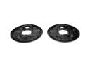 2005 Ford Explorer Brake Dust Shields
 2005 Ford Explorer Brake Line
 2005 Ford Explorer Brake Master Cylinder
 2005 Ford Explorer Parking Brake Shoe
 2005 Ford Explorer Wheel Cylinder
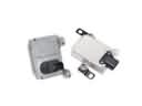 2005 Ford Explorer Yaw Sensor