FordParts
My Garage
My Account
Cart
OEM 2007 Ford Explorer Brake Pedal
Brake Pedal Pad- Select Vehicle by Model
- Select Vehicle by VIN
Select Vehicle by Model
orMake
Model
Year
Select Vehicle by VIN
For the most accurate results, select vehicle by your VIN (Vehicle Identification Number).
1 Brake Pedal found


2007 Ford Explorer Pedal Assembly Part Number: 8L2Z-2455-B
Product Specifications- Other Name: Pedal Assembly - Brake; Brake Pedal Assembly
- Replaces: 8L2Z-2455-A
- Base No.: 2455
- Item Weight: 5.10 Pounds
- Item Dimensions: 20.1 x 10.2 x 10.2 inches
- Condition: New
- Fitment Type: Direct Replacement
- SKU: 8L2Z-2455-B
- Warranty: This genuine part is guaranteed by Ford's factory warranty.
2007 Ford Explorer Brake Pedal
If you're seeking quality and affordability, look no further than our extensive inventory of genuine 2007 Ford Explorer Brake Pedal available at FordPartsDeal.com. You can confidently purchase our OEM 2007 Ford Explorer Brake Pedal as they are supported by the manufacturer's warranty and our hassle-free return policy, alongside the benefit of our fast delivery service.
2007 Ford Explorer Brake Pedal Parts Q&A
- Q: How to service and repair the brake pedal assembly on 2007 Ford Explorer?A: Service and repair procedures for the brake pedal assembly must begin with fully extending adjustable pedals when present before starting. Depower the supplemental restraint system (SRS). A discharge procedure for the stoplamp switch along with the speed control deactivator switch requires that the brake pedal stays connected to the booster rod while at rest to protect from harm. The first step should be stoplamp switch removal followed by deactivation of the speed control deactivator switch. The booster push rod clevis locking pin serves only once; remove it through a squeezing action on the locking tabs followed by a pull outward movement before discarding it. Next disconnect the brake booster rod from the brake pedal while setting it to the side. You need to disconnect both adjustable pedal motor electrical connector and accelerator pedal motor electrical connector when adjusting pedal power technology is present. Remove two bolts that secure the brake pedal bracket and discard them with four nuts from the brake booster. Before removing the brake master cylinder and brake booster assembly proceed by moving it forward from the studs. Then take out the three accelerator pedal bracket nuts while removing the two screws securing the steering column opening cover panel. Position a wheel lock to maintain stasis before you remove the steering column bolt along with the separating the steering shafts. Take out the brake pedal assembly from the vehicle system. The brake master cylinder and brake booster assembly should be positioned into the brake pedal bracket assembly after the brake pedal assembly has been installed in the vehicle. Begin by installing four new brake booster nuts before tightening these components to 22 Nm (16 ft. lbs.). Next, connect and tighten two brake pedal bracket bolts to 22 Nm (16 ft. lbs.) Then install the three accelerator pedal bracket nuts to 7 Nm (62 inch lbs.). The adjustable pedal motor electrical connector requires connection when power adjustable pedals are present and an accelerator pedal electrical connector may require similar connection. Place the brake booster push rod toward the brake pedal and fasten it with a new booster push rod clevis locking pin. Secure the steering shafts by mounting the pinch bolt and securing it to a torque of 30 Nm (22 ft. lbs.). Attach the steering column opening cover after putting in place both its screws to hold it in position. Installing the stoplamp switch and speed control deactivator switch requires that the brake pedal must be already connected to the brake booster rod in a resting position to prevent damage from occurring. Afterward install the stoplamp switch and speed control deactivator switch followed by powering up the supplemental restraint system (SRS).
Related 2007 Ford Explorer Parts
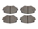 2007 Ford Explorer Brake Pads
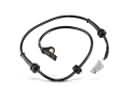 2007 Ford Explorer ABS Sensor
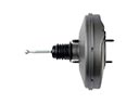 2007 Ford Explorer Brake Booster
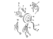
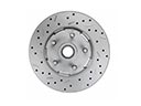 2007 Ford Explorer Brake Disc
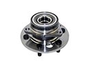 2007 Ford Explorer Wheel Hub
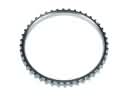 2007 Ford Explorer ABS Reluctor Ring
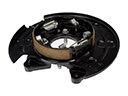 2007 Ford Explorer Brake Backing Plate
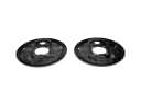 2007 Ford Explorer Brake Dust Shields
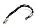 2007 Ford Explorer Brake Line
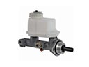 2007 Ford Explorer Brake Master Cylinder
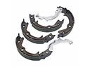 2007 Ford Explorer Parking Brake Shoe
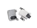 2007 Ford Explorer Yaw Sensor