My Garage
Cart

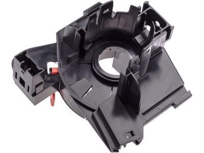
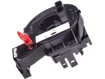
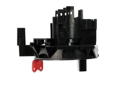
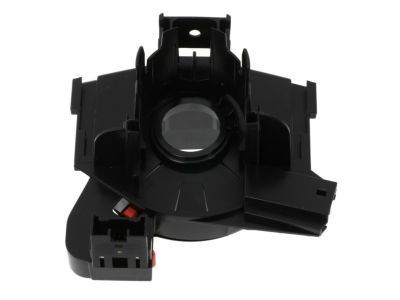
OEM 2007 Ford Focus Clock Spring

Spiral Cable Clock Spring
  • Select Vehicle by Model
  • Select Vehicle by VIN
Select Vehicle by Model
Make
Model
Year
or
Select Vehicle by VIN
For the most accurate results, select vehicle by your VIN (Vehicle Identification Number).

1 Clock Spring found

  • 2007 Ford Focus Clock Spring - 7S4Z-14A664-A
    2007 Ford Focus Clock Spring Diagram - 7S4Z-14A664-A
    View related parts

    2007 Ford Focus Clockspring
    Part Number: 7S4Z-14A664-A

    $120.74 MSRP: $185.82
    You Save: $65.08 (36%)
    Ships in 1-3 Business Days
    ADD TO CART
    Product Specifications
    • Other Name: Cover And Contact Plate Assembly; Air Bag Clockspring
    • Replaces: 4S4Z-14A664-AA
    • Base No.: 14A664
    • Item Weight: 0.90 Pounds
    • Item Dimensions: 7.9 x 6.2 x 6.2 inches
    • Condition: New
    • Fitment Type: Direct Replacement
    • SKU: 7S4Z-14A664-A
    • Warranty: This genuine part is guaranteed by Ford's factory warranty.
    More Info
    Fits the following 2007 Ford Focus Submodels:
    • S, SE, SES, ST, ZX3, ZX4, ZX4 ST, ZX5, ZXW | 4 Cyl 2.0 L GAS, 4 Cyl 2.3 L GAS

2007 Ford Focus Clock Spring

If you're seeking quality and affordability, look no further than our extensive inventory of genuine 2007 Ford Focus Clock Spring available at FordPartsDeal.com. You can confidently purchase our OEM 2007 Ford Focus Clock Spring as they are supported by the manufacturer's warranty and our hassle-free return policy, alongside the benefit of our fast delivery service.

2007 Ford Focus Clock Spring Parts Questions & Experts Answers

  • Q: What Precautions Should Be Taken When Servicing the Clock Spring Assembly to Minimize Injury Risk and Ensure Proper Installation on 2007 Ford Focus?
    A: The servicing process of Clock Spring assembly requires safety glasses to prevent air bag-related accidents and excludes the use of memory saver devices. If you disconnect the RCM fuse during an ON state of the ignition switch the air bag warning lamp should turn on as this condition indicates no SRS fault. The SRS needs operation verification for faultlessness before you give the vehicle back to the customer. A new replacement part must be installed during repairs but regular diagnostics should be restarted after reinstallation of the first part. Initialize the system depowering process to move onto driver air bag module and steering wheel removal. You should remove four screws from the instrument panel lower knee bolster while using a thin-bladed screwdriver on the clips to release the steering column upper shroud. Users of equipped vehicles can disconnect the audio control switch from the steering column lower shroud through tab malfunction and connector detachment before pullout. Start by releasing the locking lever of the steering column then remove the three retaining screws followed by lowering the shroud. Two strips of masking tape should be placed on the Clock Spring rotor to stop accidental movements when keeping the original component. Start by pushing down the locking tabs on the multi-function switches to raise them up before detaching the Clock Spring connector along with marking the spacing collar position for later use. To centralize the Clock Spring both clockwise and counterclockwise movements are required until the rotor arrow points toward the raised "V" at the 12 o'clock position (approximately 2.50 turns). Remove the tape from the Clock Spring without letting it rotate before installing it to secure its retaining tabs properly. Secure both electrical connections of the Clock Spring while attaching multifunction switches until you hear a clear locking click. The three screws secure the lower shroud while additional equipment requires the audio control switch installation along with corresponding connector connection. Fitting the upper shroud requires reattaching the instrument panel lower knee bolster with both the clip and four screws. When using a new Clock Spring never let it rotate after removing the sealing key and before installing the steering wheel since you must repeat the centralizing procedure if left unattended. The spacing collar should be installed in its proper position and all personnel should perform the centralizing process again when they return to finish installing the steering wheel. Before joining the air bag module electrical connector to the Clock Spring apply an abundant layer of XG-12 electrical grease on its connector face before reinserting the air bag module and powering up the system.

Related 2007 Ford Focus Parts