FordParts
My Garage
My Account
Cart
OEM 2007 Ford Freestar Thermostat Housing
Engine Coolant Thermostat Housing- Select Vehicle by Model
- Select Vehicle by VIN
Select Vehicle by Model
orMake
Model
Year
Select Vehicle by VIN
For the most accurate results, select vehicle by your VIN (Vehicle Identification Number).
1 Thermostat Housing found

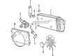
2007 Ford Freestar Thermostat Housing Part Number: F78Z-8592-BD
Product Specifications- Other Name: Connection Water Outlet; Engine Coolant Water Outlet; Thermostat Housing Cover; Water Outlet
- Base No.: 8592
- Item Weight: 0.60 Pounds
- Item Dimensions: 3.3 x 2.6 x 3.4 inches
- Condition: New
- Fitment Type: Direct Replacement
- SKU: F78Z-8592-BD
- Warranty: This genuine part is guaranteed by Ford's factory warranty.
2007 Ford Freestar Thermostat Housing
If you're seeking quality and affordability, look no further than our extensive inventory of genuine 2007 Ford Freestar Thermostat Housing available at FordPartsDeal.com. You can confidently purchase our OEM 2007 Ford Freestar Thermostat Housing as they are supported by the manufacturer's warranty and our hassle-free return policy, alongside the benefit of our fast delivery service.
2007 Ford Freestar Thermostat Housing Parts Q&A
- Q: How to service the thermostat housing on 2007 Ford Freestar?A: To maintain the thermostat housing, eliminate the cooling system, air cleaner outlet tube, and disconnect the upper radiator hose. Take out the housing bolts and get rid of the gasket. Attach the new housing bolts to a tightening of 8 Nm in two steps, then 60 degrees, and then reassemble the components and fill the cooling system.
Related 2007 Ford Freestar Parts
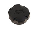 2007 Ford Freestar Coolant Reservoir Cap
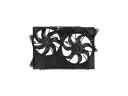 2007 Ford Freestar Cooling Fan Assembly
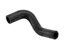 2007 Ford Freestar Cooling Hose
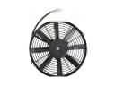 2007 Ford Freestar Engine Cooling Fan
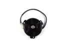 2007 Ford Freestar Fan Motor
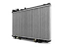 2007 Ford Freestar Radiator
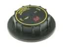 2007 Ford Freestar Radiator Cap
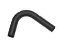 2007 Ford Freestar Radiator Hose
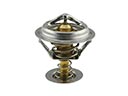 2007 Ford Freestar Thermostat
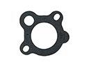 2007 Ford Freestar Thermostat Gasket
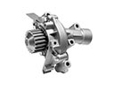 2007 Ford Freestar Water Pump
 2007 Ford Freestar Water Pump Gasket