FordParts
My Garage
My Account
Cart
OEM 2008 Ford Explorer Sport Trac Trailing Arm
Trailing Control Arm- Select Vehicle by Model
- Select Vehicle by VIN
Select Vehicle by Model
orMake
Model
Year
Select Vehicle by VIN
For the most accurate results, select vehicle by your VIN (Vehicle Identification Number).
1 Trailing Arm found


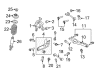
2008 Ford Explorer Sport Trac Lower Control Arm, Rear Part Number: 6L2Z-5A649-AE
$83.06 MSRP: $113.02You Save: $29.96 (27%)Product Specifications- Other Name: Arm Assembly - Rear Suspension; Suspension Control Arm, Rear Lower Rearward; Suspension Control Arm; Control Arm
- Position: Rear Lower
- Base No.: 5A649
- Item Weight: 9.20 Pounds
- Item Dimensions: 6.8 x 6.8 x 29.3 inches
- Condition: New
- Fitment Type: Direct Replacement
- Require Quantity: 2
- SKU: 6L2Z-5A649-AE
- Warranty: This genuine part is guaranteed by Ford's factory warranty.
2008 Ford Explorer Sport Trac Trailing Arm
If you're seeking quality and affordability, look no further than our extensive inventory of genuine 2008 Ford Explorer Sport Trac Trailing Arm available at FordPartsDeal.com. You can confidently purchase our OEM 2008 Ford Explorer Sport Trac Trailing Arm as they are supported by the manufacturer's warranty and our hassle-free return policy, alongside the benefit of our fast delivery service.
2008 Ford Explorer Sport Trac Trailing Arm Parts Q&A
- Q: How to service the trailing arm on 2008 Ford Explorer Sport Trac?A: In order to service the trailing arm, loosen the toe link and parking brake cable bracket bolt (10 Nm). Get rid of the trailing arm bolt and screw the new one to 300 Nm. Take out the 3 wheel knuckle bolts putting them back in at 275 Nm. Go back and make sure that all the fasteners are properly tightened.
Related 2008 Ford Explorer Sport Trac Parts
 2008 Ford Explorer Sport Trac Coil Spring Insulator
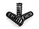 2008 Ford Explorer Sport Trac Coil Springs
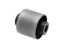 2008 Ford Explorer Sport Trac Differential Mount
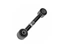 2008 Ford Explorer Sport Trac Lateral Link
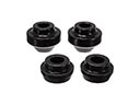 2008 Ford Explorer Sport Trac Radius Arm Bushing
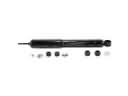 2008 Ford Explorer Sport Trac Shock Absorber
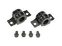 2008 Ford Explorer Sport Trac Sway Bar Bracket
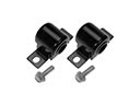 2008 Ford Explorer Sport Trac Sway Bar Bushing
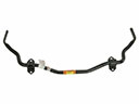 2008 Ford Explorer Sport Trac Sway Bar Kit
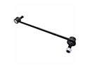 2008 Ford Explorer Sport Trac Sway Bar Link
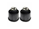 2008 Ford Explorer Sport Trac Trailing Arm Bushing
 2008 Ford Explorer Sport Trac Wheel Cover