FordParts
My Garage
My Account
Cart
OEM 2008 Ford F-150 Clock Spring
Spiral Cable Clock Spring- Select Vehicle by Model
- Select Vehicle by VIN
Select Vehicle by Model
orMake
Model
Year
Select Vehicle by VIN
For the most accurate results, select vehicle by your VIN (Vehicle Identification Number).
1 Clock Spring found


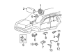
2008 Ford F-150 Clockspring Part Number: 8L3Z-14A664-A
Product Specifications- Other Name: Cover And Contact Plate Assembly; Air Bag Clockspring
- Replaces: 2L2Z-14A664-AB, 7L3Z-14A664-A
- Base No.: 14A664
- Item Weight: 0.90 Pounds
- Item Dimensions: 8.2 x 6.1 x 4.5 inches
- Condition: New
- Fitment Type: Direct Replacement
- SKU: 8L3Z-14A664-A
- Warranty: This genuine part is guaranteed by Ford's factory warranty.
2008 Ford F-150 Clock Spring
If you're seeking quality and affordability, look no further than our extensive inventory of genuine 2008 Ford F-150 Clock Spring available at FordPartsDeal.com. You can confidently purchase our OEM 2008 Ford F-150 Clock Spring as they are supported by the manufacturer's warranty and our hassle-free return policy, alongside the benefit of our fast delivery service.
2008 Ford F-150 Clock Spring Parts Q&A
- Q: How to Service and Repair the Clock Spring Assembly to Ensure the Supplemental Restraint System (SRS) is Operational on 2008 Ford F-150?A: Activation of the SRS must occur prior to the servicing of the Clock Spring assembly. Unassemble the driver air bag module and steering wheel and disconnect Clock Spring. Check and change the mounting bracket in case broken. Installation requirements include centralizing the Clock Spring and reconnecting components and powering the SRS once more.
Related 2008 Ford F-150 Parts
 2008 Ford F-150 Air Bag
 2008 Ford F-150 Air Bag Control Module
 2008 Ford F-150 Air Bag Sensor
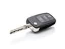 2008 Ford F-150 Car Key
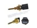 2008 Ford F-150 Cylinder Head Temperature Sensor
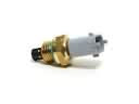 2008 Ford F-150 Intake Manifold Temperature Sensor
 2008 Ford F-150 Neutral Safety Switch
 2008 Ford F-150 Relay
 2008 Ford F-150 Spark Plug
 2008 Ford F-150 TPMS Sensor
 2008 Ford F-150 Vehicle Speed Sensor
 2008 Ford F-150 Window Switch