FordParts
My Garage
My Account
Cart
OEM 2009 Ford Escape Steering Shaft
Steering Stem Shaft- Select Vehicle by Model
- Select Vehicle by VIN
Select Vehicle by Model
orMake
Model
Year
Select Vehicle by VIN
For the most accurate results, select vehicle by your VIN (Vehicle Identification Number).
1 Steering Shaft found


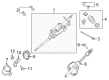
2009 Ford Escape Lower Shaft Part Number: 9L8Z-3B676-A
$173.49 MSRP: $285.45You Save: $111.96 (40%)Ships in 1-2 Business DaysProduct Specifications- Other Name: Shaft Assembly; Steering Shaft, Lower; Steering Shaft
- Manufacturer Note: Steering Shaft
- Replaces: 8L8Z-3B676-A
- Base No.: 3524
- Item Weight: 3.30 Pounds
- Item Dimensions: 17.9 x 6.3 x 6.4 inches
- Condition: New
- Fitment Type: Direct Replacement
- SKU: 9L8Z-3B676-A
- Warranty: This genuine part is guaranteed by Ford's factory warranty.
2009 Ford Escape Steering Shaft
If you're seeking quality and affordability, look no further than our extensive inventory of genuine 2009 Ford Escape Steering Shaft available at FordPartsDeal.com. You can confidently purchase our OEM 2009 Ford Escape Steering Shaft as they are supported by the manufacturer's warranty and our hassle-free return policy, alongside the benefit of our fast delivery service.
2009 Ford Escape Steering Shaft Parts Q&A
- Q: How to service and repair the Steering Shaft on 2009 Ford Escape?A: To fix the steering column shaft, take out the trim and side finish panel, un-wire harnesses and find the coupling bolt. Take out and change the bolt with correct torque. To avoid Clock Spring damage, rotate the shaft not. Take off the shaft and dash seal, checking and inspecting it, and repeat the process.
Related 2009 Ford Escape Parts
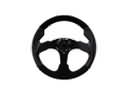 2009 Ford Escape Steering Wheel
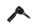 2009 Ford Escape Tie Rod
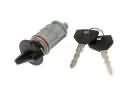 2009 Ford Escape Ignition Lock Cylinder
 2009 Ford Escape Rack And Pinion
 2009 Ford Escape Steering Column
 2009 Ford Escape Turn Signal Switch
 2009 Ford Escape Rack and Pinion Boot
 2009 Ford Escape Steering Column Cover
 2009 Ford Escape Steering Column Seal
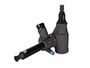 2009 Ford Escape Steering Gear Box
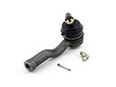 2009 Ford Escape Tie Rod End