FordParts
My Garage
My Account
Cart
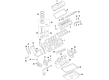
OEM 2009 Ford F-150 Timing Cover
Engine Timing Cover- Select Vehicle by Model
- Select Vehicle by VIN
Select Vehicle by Model
orMake
Model
Year
Select Vehicle by VIN
For the most accurate results, select vehicle by your VIN (Vehicle Identification Number).
2 Timing Covers found


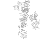
2009 Ford F-150 Timing Cover, Front Part Number: 7L3Z-6019-B
$224.73 MSRP: $330.00You Save: $105.27 (32%)Product Specifications- Other Name: Cover - Cylinder Front; Engine Timing Cover; Front Cover
- Position: Front
- Replaces: 4L3Z-6019-AA
- Base No.: 6019
- Item Weight: 12.40 Pounds
- Item Dimensions: 24.8 x 21.6 x 8.3 inches
- Condition: New
- Fitment Type: Direct Replacement
- SKU: 7L3Z-6019-B
- Warranty: This genuine part is guaranteed by Ford's factory warranty.

2009 Ford F-150 Timing Cover, Front Passenger Side Part Number: 7R3Z-6019-A
$170.61 MSRP: $248.33You Save: $77.72 (32%)Product Specifications- Other Name: Cover - Cylinder Front; Engine Timing Cover; Front Cover
- Position: Front Passenger Side
- Replaces: 4R3Z-6019-BG, 7R3Z-6019-BA
- Base No.: 6019
- Item Weight: 14.80 Pounds
- Item Dimensions: 22.7 x 21.2 x 7.4 inches
- Condition: New
- Fitment Type: Direct Replacement
- SKU: 7R3Z-6019-A
- Warranty: This genuine part is guaranteed by Ford's factory warranty.
2009 Ford F-150 Timing Cover
If you're seeking quality and affordability, look no further than our extensive inventory of genuine 2009 Ford F-150 Timing Cover available at FordPartsDeal.com. You can confidently purchase our OEM 2009 Ford F-150 Timing Cover as they are supported by the manufacturer's warranty and our hassle-free return policy, alongside the benefit of our fast delivery service.
2009 Ford F-150 Timing Cover Parts Q&A
- Q: How to Service and Repair the Engine Front Timing Cover on 2009 Ford F-150?A: Service and repair operations on the engine front cover start with placing the vehicle on a hoist while it remains in neutral. Start by removing both the RH and LH valve covers together with removing the engine cooling fan. Following these steps you should loosen bolts on the four coolant pump pulley then rotate the tensioner clockwise to remove the accessory drive belt. After the four bolts securing the coolant pump pulley you should drain the engine oil through the drain plug before reinstalling the plug at 23 Nm (17 lb-ft) torque. After removing the pushpin you should rotate the lower cooling fan shroud upwards until it secures into place. First detach the bolt on the starter wiring harness bracket while putting aside the transmission cooler tube support bracket and starter wiring harness support bracket. Then separate the crankshaft position (CKP) sensor electrical connector. Discard the nut that holds the power steering pressure (PSP) hose support bracket while also taking off the crankshaft pulley bolt with its washer then throwing out the bolt. A 3-jaw puller allows the technician to take off the crankshaft pulley but a crankshaft front seal remover is required to remove the crankshaft front seal. Begin by taking off the three accessory drive idler pulleys and their respective three bolts as well as the three tensioner bolts securing the accessory drive belt tensioner. Proceed with removing first the skid plate bolts when equipped along with the four bolts securing the front oil pan. The wiring harness retainer requires removal first before taking two bolts and a stud bolt to place the power steering pump in a safe location. Detach the electrical connectors of the RH and LH camshaft position (CMP) sensors before removing their specific bolts while setting aside radio ignition interference capacitors. The engine front cover needs nine bolts and six stud bolts removal to separate it from the dowel system while you need to discard the three engine front cover gaskets. Remove the bolt from the CKP sensor as well as discard the O-ring seal. The sealing surfaces require cleaning through the use of a plastic scraping tool and silicone gasket remover applied with no abrasive materials. For the CKP sensor installation, use a new O-ring seal which must be lubricated with engine oil before tightening bolt to 10 Nm torque (89 lb-in). Position the engine front cover onto the dowels after applying silicone gasket and sealant on the cylinder head-to-cylinder block and oil pan-to-cylinder block surfaces where the gaskets should be properly installed. You should first tighten the 15 fasteners by hand before moving to two staged torques where fasteners 6 and 7 reach 25 Nm but 48 Nm. Firmly install the four bolts at 20 Nm strength before advancing the torque another 60 degrees. Next attach the CKP sensor electric connector while tightening starter wiring harness support bracket along with transmission cooler tube support bracket nut to 10 Nm (89 lb-in) torque before installing the starter wiring harness bracket bolt at the starter also at 10 Nm (89 lb-in). Add a thin layer of clean engine oil on the engine front cover along with the new crankshaft seal inner tip followed by installation using the front cover oil seal installer, crankshaft front seal installer along with the crankshaft vibration damper installer. The Woodruff key slot on the crankshaft pulley receives silicone gasket and sealant treatment before using the crankshaft vibration damper installer to install the pulley. The first step is to install the washer onto the new crankshaft pulley bolt before tightening it finger-tight. Proceed with a four-step tightening sequence starting with 120 Nm (89 lb-ft) torque followed by a 360-degree loosen and re-tightening to 50 Nm (37 lb-ft) before completing with a further torque of 90 degrees. Lower the lower cooling fan shroud downward following installation of the position tab retainer until the lock happens and then secure its position using the pushpin. After installing the accessory drive belt tensioner you must tighten its three bolts to 25 Nm (18 lb-ft). Then install all three accessory drive idler pulleys and their respective bolts with a torque of 25 Nm (18 lb-ft). Fasten all four bolts on the coolant pump pulley with loose tension and put on the skid plate and its four bolts at 25 Nm (18 lb-ft). The power steering pump requires a stud bolt installation with two bolts after which engineers must tighten both the bolts and the stud constantly to 25 Nm (18 lb-ft). Then connect the engine wiring harness to the power steering pump stud bolt. Secure the PSP hose support bracket with its nut and secure by turning it to 40 Nm (30 lb-ft). You must prepare the RH CMP sensor O-ring by coating it with engine oil before installing it with its bolt which needs tightening force of 10 Nm (89 lb-in) and then connecting the RH CMP sensor electrical connector. Place the RH radio ignition interference capacitor before attaching its nut which should be tightened to 25 Nm (18 lb-ft). Then apply oil to the O-ring seal of the LH CMP sensor as you install it and tighten it to 10 Nm (89 lb-in). Finally, reconnect the LH CMP sensor electrical connector. The LH radio ignition interference capacitor requires installation with its corresponding nut which must be tightened to 10 Nm (89 lb-in). To install the accessory drive belt first rotate the tensioner clockwise and after that tighten the four coolant pump pulley bolts to 25 Nm (18 lb-ft). To finish the installation return the engine cooling fan and then install both the LH and RH valve covers. For the last step you must fill the crankcase with fresh engine oil and then complete the misfire monitor neutral profile correction by following instructions on a scan tool.
Related 2009 Ford F-150 Parts
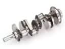 2009 Ford F-150 Crankshaft
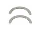 2009 Ford F-150 Crankshaft Thrust Washer Set
 2009 Ford F-150 Cylinder Head Bolts
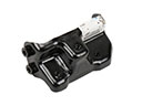 2009 Ford F-150 Engine Mount Bracket
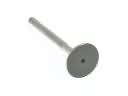 2009 Ford F-150 Exhaust Valve
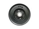 2009 Ford F-150 Harmonic Balancer
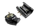 2009 Ford F-150 Motor And Transmission Mount
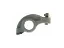 2009 Ford F-150 Rocker Arm
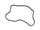 2009 Ford F-150 Timing Chain
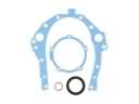 2009 Ford F-150 Timing Cover Gasket
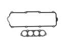 2009 Ford F-150 Valve Cover Gasket
 2009 Ford F-150 Valve Stem Seal