FordParts
My Garage
My Account
Cart
OEM 2009 Ford Taurus Clock Spring
Spiral Cable Clock Spring- Select Vehicle by Model
- Select Vehicle by VIN
Select Vehicle by Model
orMake
Model
Year
Select Vehicle by VIN
For the most accurate results, select vehicle by your VIN (Vehicle Identification Number).
1 Clock Spring found


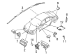
2009 Ford Taurus Clockspring Part Number: 8G1Z-14A664-A
$108.95 MSRP: $158.58You Save: $49.63 (32%)Product Specifications- Other Name: Cover And Contact Plate Assembly; Air Bag Clockspring
- Base No.: 14A664
- Item Weight: 1.20 Pounds
- Item Dimensions: 6.1 x 6.2 x 4.6 inches
- Condition: New
- Fitment Type: Direct Replacement
- SKU: 8G1Z-14A664-A
- Warranty: This genuine part is guaranteed by Ford's factory warranty.
2009 Ford Taurus Clock Spring
If you're seeking quality and affordability, look no further than our extensive inventory of genuine 2009 Ford Taurus Clock Spring available at FordPartsDeal.com. You can confidently purchase our OEM 2009 Ford Taurus Clock Spring as they are supported by the manufacturer's warranty and our hassle-free return policy, alongside the benefit of our fast delivery service.
2009 Ford Taurus Clock Spring Parts Q&A
- Q: How to Service and Repair the Clock Spring Assembly on 2009 Ford Taurus?A: In order to fix the Clock Spring assembly, make sure that the air bag warning light is turned on and the SRS is not faulty. Align position road wheels, take off driver air bag module, steering wheel and Clock Spring. Before installing Center the Clock Spring, without over-rotating. Install after centering.
Related 2009 Ford Taurus Parts
 2009 Ford Taurus Brake Light Switch
 2009 Ford Taurus ABS Pump And Motor Assembly
 2009 Ford Taurus Air Bag
 2009 Ford Taurus Air Bag Control Module
 2009 Ford Taurus Air Bag Sensor
 2009 Ford Taurus Antenna Base
 2009 Ford Taurus Antenna Cable
 2009 Ford Taurus Body Control Module
 2009 Ford Taurus Knock Sensor
 2009 Ford Taurus Mirror Switch
 2009 Ford Taurus Oil Pressure Switch
 2009 Ford Taurus Oxygen Sensors