FordParts
My Garage
My Account
Cart
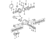
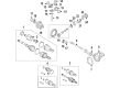
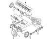
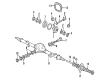
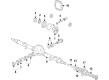
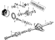
OEM Ford E-250 Econoline Differential
Front Differential- Select Vehicle by Model
- Select Vehicle by VIN
Select Vehicle by Model
orMake
Model
Year
Select Vehicle by VIN
For the most accurate results, select vehicle by your VIN (Vehicle Identification Number).
14 Differentials found


Ford E-250 Econoline Differential Case Part Number: 9L3Z-4204-B
$122.38 MSRP: $173.85You Save: $51.47 (30%)Ships in 1-3 Business Days


Ford E-250 Econoline Differential Case, Front Part Number: 9L3Z-4204-A
$141.08 MSRP: $204.62You Save: $63.54 (32%)Ships in 1-3 Business Days
Ford E-250 Econoline Differential Case Part Number: F7UZ-4204-AD
$233.05 MSRP: $335.08You Save: $102.03 (31%)Ships in 1-3 Business Days
Ford E-250 Econoline Differential Case Part Number: YC2Z-4204-AA
$241.29 MSRP: $346.92You Save: $105.63 (31%)
Ford E-250 Econoline Differential Case Part Number: F7UZ-4204-AC
$236.08 MSRP: $320.00You Save: $83.92 (27%)Ships in 1-3 Business Days
Ford E-250 Econoline Differential Case Part Number: F7UZ-4204-AA
$257.19 MSRP: $348.62You Save: $91.43 (27%)Ships in 1-3 Business Days
Ford E-250 Econoline Differential Case Part Number: F7UZ-4204-AB
$338.34 MSRP: $458.62You Save: $120.28 (27%)Ships in 1-3 Business Days
Ford E-250 Econoline Ring & Pinion Part Number: 1C2Z-4209-FA
$423.36 MSRP: $573.85You Save: $150.49 (27%)
Ford E-250 Econoline Ring & Pinion Part Number: 1C2Z-4209-CA
$468.19 MSRP: $634.62You Save: $166.43 (27%)
Ford E-250 Econoline Differential Case Part Number: F7UZ-4204-AF
$262.47 MSRP: $377.38You Save: $114.91 (31%)Ships in 1-2 Business DaysFord E-250 Econoline Ring & Pinion Part Number: YC2Z-4209-BA
$471.23 MSRP: $682.00You Save: $210.77 (31%)Ford E-250 Econoline Differential Case Part Number: F7UZ-4204-AE
$137.40 MSRP: $184.62You Save: $47.22 (26%)Ships in 1-3 Business Days
Ford E-250 Econoline Ring & Pinion Part Number: 1C2Z-4209-DA
$255.38 MSRP: $346.15You Save: $90.77 (27%)Ford E-250 Econoline Ring & Pinion Part Number: 1C2Z-4209-AA
Ford E-250 Econoline Differential
OEM Differential boasts unmatched quality. Each part goes through full quality checks. They adhere to Ford's official factory standards. These steps remove flaws and inconsistencies. So you can get Differential with long life and a perfect fit. Come to our website and find genuine Ford E-250 Econoline parts. We keep a wide inventory of OEM E-250 Econoline parts at the highly affordable prices. It's easy to search, compare, and pick what you need. You'll love the clear info and simple checkout. We offer top-rated customer service, and we reply fast. We also ship promptly to ensure your order arrives on time.
Ford E-250 Econoline Differential Parts and Q&A
- Q: How to service and repair the differential case and ring gear for the 70 Limited Slip on Ford E-250 Econoline?A:The first step involves match-marking the differential case flange and button halves and the differential pinion shafts together with their corresponding ramps before starting Model 70 Limited Slip differential case and ring gear service work. The differential ring gear should be removed only if needed. The differential case can be properly held through the use of an installed Axle Shaft in a vise whose splines must not reach beyond three inches above the jaws. Place the differential assembly on a bench after loosening its bolts but leave the bolts in position and remove the bolts as well as the button half of the differential case. Separate and carefully organize the differential side gear together with side gear ring and rear axle disc and plate kit and differential pinion gears and pinion shafts for correct assembly. Put together the pinion flange assembly by placing the side gear ring and rear axle disc and plate kit received from the flange half of the differential case. Check the clutch plates and discs for cracks, excessive wear and distortion before installing new rear axle disc and plate components on each side whenever you discard any clutch plates or discs. Thorough inspection must include an assessment of the differential pinion shafts alongside ramp surfaces and a close look at the side gear together with its pinion gear teeth and side gear races for both wear and damage. Friction modifier should be used to soak each clutch pack component for a period of twenty minutes before assembly. Set the side gear ring inside the pinion flange before applying lubricant to both the rear axle disc and plate kit while positioning it onto the side gear ring. Examine that the gear splines on the side component correctly link to clutch pack splines when the differential side gear reaches complete insertion. Place the side gear ring and rear axle disc and plate kit together with the side gear within the differential case flange half. Vehicles operating near GVW may need to combine rear axle disc and plate with the clutch disc adjacent to the differential side gear ring to create two clutch plates which decrease wheel rotational torque by 40 percent. The clutch press plate lugs need alignment before installing the side gear ring along with clutch pack and differential side gear inside the button half of the differential case. Property marks established during dismantling should guide you when placing differential pinion shafts and gears into both pieces of differential case housing. The button half of the differential case requires placement onto the flange half with proper attention given to clean dry bolts before installation. Equal and alternating steps should be used when bolting. Each differential pinion shaft fits properly on its ramp so that clearance should not exceed 0.254 mm (0.010 inch) measurements at all four ends. Reinstall the differential ring gear before tightening its Grade 9 bolts to 176 Nm (130 ft. lbs.).

Related Ford E-250 Econoline Parts
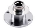 Ford E-250 Econoline CV Joint Companion Flange
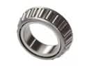 Ford E-250 Econoline Differential Bearing
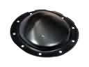 Ford E-250 Econoline Differential Cover
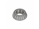 Ford E-250 Econoline Differential Pinion Bearing
 Ford E-250 Econoline Drive Shaft
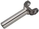 Ford E-250 Econoline Driveshaft Yokes
 Ford E-250 Econoline Pinion Bearing
 Ford E-250 Econoline Slip Yoke
 Ford E-250 Econoline Transfer Case Bearing
 Ford E-250 Econoline Transfer Case Shim
 Ford E-250 Econoline Universal Joint