FordParts
My Garage
My Account
Cart
OEM Ford Explorer Sport Brake Shoe Set
Brake Shoe- Select Vehicle by Model
- Select Vehicle by VIN
Select Vehicle by Model
orMake
Model
Year
Select Vehicle by VIN
For the most accurate results, select vehicle by your VIN (Vehicle Identification Number).
1 Brake Shoe Set found
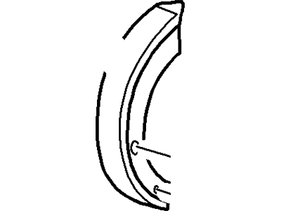
Ford Explorer Sport Brake Shoes Part Number: 7U2Z-2V753-A
Ford Explorer Sport Brake Shoe Set
OEM Brake Shoe Set boasts unmatched quality. Each part goes through full quality checks. They adhere to Ford's official factory standards. These steps remove flaws and inconsistencies. So you can get Brake Shoe Set with long life and a perfect fit. Come to our website and find genuine Ford Explorer Sport parts. We keep a wide inventory of OEM Explorer Sport parts at the highly affordable prices. It's easy to search, compare, and pick what you need. You'll love the clear info and simple checkout. We offer top-rated customer service, and we reply fast. We also ship promptly to ensure your order arrives on time.
Ford Explorer Sport Brake Shoe Set Parts and Q&A
- Q:How to service and repair the Brake Shoe Set on Ford Explorer Sport?A:The brake shoe servicing process begins with brake drum removal followed by inspection of the rear brake assembly to check for excessive leakage from the rear wheel cylinder and contamination on the brake shoes and linings and minimum thickness above the Backing Plate or rivets and heat discoloration on the springs and the adjusting lever's contact with the brake adjuster screw must be checked. Mark the positions of the short and long brake shoe retracting springs before you take out these springs. The mechanic needs to disconnect the brake shoe adjusting lever cable before moving on to remove the cable guide then the adjusting lever return spring before extracting the brake shoe adjusting lever and brake shoe adjusting screw spring and finally the brake adjuster screw assembly. The parking brake link spring along with the brake parking spring retainer will separate from the parking brake strut, thus remove the brake shoe anchor pin guide plate, parking brake strut and parking brake lever pin retainer. The brake shoe hold-down springs and pins must be detached first before removing the rear brake shoes and linings. To install the brakes use Silicone Brake Caliper Grease and Dielectric Compound D7AZ-19A331-A (Motorcraft WA-10) or an equivalent silicone compound that meets Ford specification ESE-M1C171-A. The parking brake lever should then be connected to the rear brake shoe and lining with the parking brake lever pin retainer securing it before installing the brake shoe hold-down spring pins and springs. Put in place the parking brake strut then the link spring and spring retainer before adding the short brake shoe retracting spring. Position the brake shoe adjusting lever cable inside the cable guide groove before installing both the retracting spring and cable guide of the long brake shoe. Assume control of the brake adjuster screw assembly for disassembly before adding silicone grease and performing reassembly while following standards that require R or L stamping on the brake adjuster screw socket ends for installation sequence determination. Position the brake adjuster screw assembly followed by installation of the brake shoe adjusting screw spring and correct placement of the brake shoe adjusting lever and all its components. Check the automatic self-adjuster functionality through cable manipulation of the brake shoe adjusting lever while monitoring brake shoe adjuster assembly rotation until it enters the following notch after cable release. Adjustment of brakes should occur before installing the brake drum.
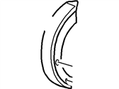
Related Ford Explorer Sport Parts
 Ford Explorer Sport ABS Sensor
 Ford Explorer Sport Backing Plate
 Ford Explorer Sport Brake Booster
 Ford Explorer Sport Brake Caliper
 Ford Explorer Sport Brake Caliper Repair Kit
 Ford Explorer Sport Brake Dust Shields
 Ford Explorer Sport Brake Line
 Ford Explorer Sport Brake Pads
 Ford Explorer Sport Brake Rotor
 Ford Explorer Sport Hydraulic Hose
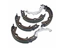 Ford Explorer Sport Parking Brake Shoes
 Ford Explorer Sport Wheel Bearing