FordParts
My Garage
My Account
Cart
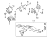
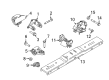
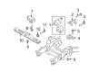
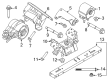
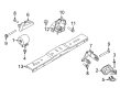
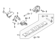
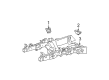
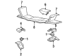
OEM Ford F-150 Engine Mount
Engine Motor Mount- Select Vehicle by Model
- Select Vehicle by VIN
Select Vehicle by Model
orMake
Model
Year
Select Vehicle by VIN
For the most accurate results, select vehicle by your VIN (Vehicle Identification Number).
134 Engine Mounts found


Ford F-150 Motor Mount, Driver Side Part Number: AL3Z-6038-E
$131.87 MSRP: $203.50You Save: $71.63 (36%)Ships in 1-2 Business Days

Ford F-150 Motor Mount, Passenger Side Part Number: BL3Z-6038-J
$180.11 MSRP: $262.17You Save: $82.06 (32%)


Ford F-150 Motor Mount, Passenger Side Part Number: AL3Z-6038-B
$180.11 MSRP: $262.17You Save: $82.06 (32%)


Ford F-150 Transmission Mount Part Number: FL3Z-6068-E
$105.34 MSRP: $153.33You Save: $47.99 (32%)Ships in 1-2 Business Days

Ford F-150 Motor Mount, Driver Side Part Number: BL3Z-6038-E
$81.49 MSRP: $118.62You Save: $37.13 (32%)Ships in 1-2 Business Days


Ford F-150 Motor Mount Part Number: 9L3Z-6038-A
$94.58 MSRP: $137.67You Save: $43.09 (32%)
Ford F-150 Motor Mount, Driver Side Part Number: BL3Z-6038-C
$102.45 MSRP: $157.67You Save: $55.22 (36%)Ships in 1-3 Business Days

Ford F-150 Transmission Mount Part Number: HL3Z-6068-A
$127.21 MSRP: $185.17You Save: $57.96 (32%)

Ford F-150 Motor Mount, Driver Side Part Number: DL3Z-6038-B
$139.69 MSRP: $203.33You Save: $63.64 (32%)Ships in 1-3 Business Days


Ford F-150 Motor Mount, Driver Side Part Number: BL3Z-6038-A
$140.84 MSRP: $205.00You Save: $64.16 (32%)


Ford F-150 Motor Mount, Passenger Side Part Number: HL3Z-6038-K
$198.09 MSRP: $288.33You Save: $90.24 (32%)Ships in 1-3 Business Days

Ford F-150 Transmission Mount Part Number: 4L3Z-6068-A
$145.42 MSRP: $211.67You Save: $66.25 (32%)

Ford F-150 Transmission Mount Part Number: AL3Z-6068-B
$161.22 MSRP: $234.67You Save: $73.45 (32%)Ships in 1-3 Business Days


Ford F-150 Transmission Mount Part Number: JL3Z-6068-F
$135.11 MSRP: $196.67You Save: $61.56 (32%)Ships in 1-2 Business Days

Ford F-150 Transmission Mount Part Number: 5L3Z-6068-DA
$169.46 MSRP: $246.67You Save: $77.21 (32%)


Ford F-150 Motor Mount, Passenger Side Part Number: BL3Z-6038-G
$173.81 MSRP: $253.00You Save: $79.19 (32%)Ships in 1-2 Business Days

Ford F-150 Motor Mount Part Number: 9L3Z-6038-C
$245.16 MSRP: $360.00You Save: $114.84 (32%)


Ford F-150 Motor Mount, Passenger Side Part Number: F4TZ-6038-A
$29.38 MSRP: $40.64You Save: $11.26 (28%)Ships in 1-2 Business Days

Ford F-150 Mount Bracket, Driver Side Part Number: 9L3Z-6038-B
$98.87 MSRP: $143.92You Save: $45.05 (32%)


Ford F-150 Transmission Mount Part Number: BL3Z-6068-D
$139.80 MSRP: $203.50You Save: $63.70 (32%)
| Page 1 of 7 |Next >
1-20 of 134 Results
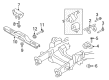
Ford F-150 Engine Mount
OEM Engine Mount boasts unmatched quality. Each part goes through full quality checks. They adhere to Ford's official factory standards. These steps remove flaws and inconsistencies. So you can get Engine Mount with long life and a perfect fit. Come to our website and find genuine Ford F-150 parts. We keep a wide inventory of OEM F-150 parts at the highly affordable prices. It's easy to search, compare, and pick what you need. You'll love the clear info and simple checkout. We offer top-rated customer service, and we reply fast. We also ship promptly to ensure your order arrives on time.
Ford F-150 Engine Mount Parts and Q&A
- Q: How to remove and replace the Engine Mount insulators on Ford F-150?A:First position the vehicle on a hoist with neutral transmission position before starting the engine support insulator replacement process. Please start by taking out both the Intake Manifold and cooling fan before removing the oil level indicator together with its tube bolt. First install engine support bracket with engine support bar and support hook before discarding exhaust manifold-to-dual converter Y-pipe nuts and taking out the two transmission mount nuts. The sequence starts with Starter removal then proceeds to detach the accessory Drive Belt from the A/C compressor pulley while the tensioner rotates clockwise before setting the A/C compressor to the side after removing its 3 bolts. On vehicles equipped with four-wheel drive the front driveshaft CV joint needs to be marked and the axle must be supported to avoid CV joint damage before the removal of 6 CV joint bolts with discarding of the nuts. Proceed to remove first the 2 RH engine support insulator nuts while unstowing the studs before moving on to extract the LH engine support insulator through bolt. Use support equipment to lift the engine and then remove the through bolt of the right hand engine support insulator followed by the 3 bolts on the right hand engine support insulator bracket to access and remove both components and their bracket. The LH engine support insulator along with its bolts needs to be removed if required. First clean the mating surfaces of engine support insulator bracket and cylinder block then position the LH engine support insulator bracket before installing the 3 bolts with threadlock while tightening them to 63 Nm (46 lb-ft). Install the LH engine support insulator by cleaning its mating surfaces with threadlock bolts which should be tightened to 175 Nm (129 lb-ft). Connect the RH engine support insulator bracket to its frame surface after cleaning then install its brackets with threadlock until reaching 63 Nm (46 lb-ft) torque. Install the threadlocked through bolt of the RH engine support insulator loosely. Lower the engine while connecting the studs of the RH support insulator until torque reaches 15 Nm (133 lb-in) with threadlock. Hand tools should be used to install RH engine support insulator nuts with threadlock by tightening to 250 Nm (184 lb-ft). The installation of the LH engine support insulator through bolt with threadlock begins with tightening it to 350 Nm (258 lb-ft) while following up with equal torque on the RH engine support insulator through bolt. Platform and place the A/C compressor before securing it with three bolts that should be tightened to 25 Nm (18 lb-ft). The accessory drive tensioner must be rotated until the A/C compressor pulley accepts the belt and then the starter component must be reinstalled. The front axle CV joint should be aligned with the index mark in 4WD vehicles before adding the 3 washers and 6 new bolts which need to be torqued to 19 Nm (168 lb-in). Mount the transmission mount nuts with 103 Nm (76 lb-ft) torque and tighten all new exhaust manifold-to-dual converter Y-pipe nuts to 40 Nm (30 lb-ft). After mounting the oil level indicator tube bolt and the oil level indicator you must apply 10 Nm (89 lb-in) torque followed by installation of the engine cooling fan then the intake manifold.

Related Ford F-150 Parts
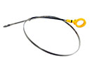 Ford F-150 Dipstick
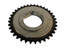 Ford F-150 Balance Shaft Gear
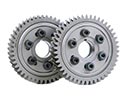 Ford F-150 Cam Gear
 Ford F-150 Camshaft Seal
 Ford F-150 Crankshaft Pulley
 Ford F-150 Crankshaft Seal
 Ford F-150 Cylinder Head
 Ford F-150 Cylinder Head Gasket
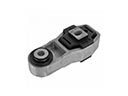 Ford F-150 Engine Mount Torque Strut
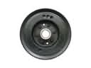 Ford F-150 Harmonic Balancer
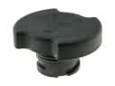 Ford F-150 Oil Filler Cap
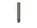 Ford F-150 Pushrod