FordParts
My Garage
My Account
Cart
OEM Ford Five Hundred Timing Chain Tensioner
Engine Timing Chain Tensioner- Select Vehicle by Model
- Select Vehicle by VIN
Select Vehicle by Model
orMake
Model
Year
Select Vehicle by VIN
For the most accurate results, select vehicle by your VIN (Vehicle Identification Number).
1 Timing Chain Tensioner found

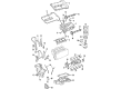
Ford Five Hundred Tensioner Part Number: YF1Z-6L266-BA
$62.06 MSRP: $90.33You Save: $28.27 (32%)
Ford Five Hundred Timing Chain Tensioner
OEM Timing Chain Tensioner boasts unmatched quality. Each part goes through full quality checks. They adhere to Ford's official factory standards. These steps remove flaws and inconsistencies. So you can get Timing Chain Tensioner with long life and a perfect fit. Come to our website and find genuine Ford Five Hundred parts. We keep a wide inventory of OEM Five Hundred parts at the highly affordable prices. It's easy to search, compare, and pick what you need. You'll love the clear info and simple checkout. We offer top-rated customer service, and we reply fast. We also ship promptly to ensure your order arrives on time.
The Timing Chain Tensioner is a significant component that brings the added reliability and performance in the Ford Five Hundred, manufactured between the years 2004 to 2007. This Timing Chain Tensioner helps to keep the tension of the timing chain optimum so that the engine can perform as required without any trouble. The Timing Chain Tensioner ensures timely elimination of slack in the timing chain hence the key to engine performance, frequently ensure for the requite of a car's safety and lifespan. As a part part of the car, this Timing Chain Tensioner is compatible with different models of the Ford Five Hundred; thanks to flexibility in the number of tends and configurations of the engine designs. The Ford Five Hundred has a rather large amount of space inside the car and several safety features, the reliability of the Timing Chain Tensioner adds another factor to make the engine parts move in unison. First of all, the Timing Chain Tensioner is made up of the newest materials and has as accurate a design as it is possible in the automotive industry. The constant provision of tension under what- SoY conditions assists in efficient fuel consumption and little emissions that are friendly to the atmosphere in compliance with modern standard automobiles. In conclusion, the Timing Chain Tensioner is one other phenomenon that is evident and shows that Ford Company is passionate on their Ford Five Hundred vehicles engineering firm.
Ford Five Hundred Timing Chain Tensioner Parts and Q&A
- Q: How to service and repair the timing chain tensioner on Ford Five Hundred?A:The process for servicing timing chain tensioners requires cleaning the work area to avoid oil or coolant passage entry of foreign substances that cause catastrophic engine failure. First eliminate the engine front cover then take out the ignition pulse wheel while making certain that the pulse wheel features its keyway oriented to the slot bearing the markings "30" or "30RFF" (orange in color). Begin the procedure by installing the damper bolt before you remove the two Spark Plugs located on the LH and RH positions of the engine. Open the crankshaft clockwise so its keyway becomes visible at 11 o'clock while the engine reaches top dead center (TDC) for the first cylinder. Check the Camshaft alignment once again if the crankshaft needs another clockwise rotation to achieve the correct location. Proceed with clockwise crankshaft rotation for 120 degrees until both RH camshafts arrive at neutral position and inspect their alignment status. First remove the RH timing chain tensioner arm then proceed to remove the accompanying bolts as well as the tensioner and tensioner arm itself. The following components need removal starting with timing chain guide, bolts, and RH timing chain. A counter-clockwise crankcase rotation of 60 degrees must be performed to establish the crankcase keyway at 11 o'clock mark as the LH camshafts should now rest in their neutral position. The installation process begins with removing the LH timing chain tensioner arm and progress to the LH timing chain and timing chain guide. Finally you can remove the damper bolt and crankshaft sprocket. Install components only when their alignment with timing drive components achieves correct placement to prevent serious engine damage. Position the crankshaft sprocket while its timing marks should be visible to the outside. Use a small pick to maintain the ratchet stem while holding the ratchet lock mechanism in a position separate from the ratchet stem after positioning the chain tensioner inside a soft-jawed vise. Use a 1.5 mm (0.05 inch) wire or paper clip to retain the tensioner piston while it is bottomed in its bore after compressing the tensioner by hand without letting go of the ratchet stem. The procedure requires marking the timing marks on LH and RH timing chains while identifying any link as the crankshaft timing mark and counting links 29 and 42. First ensure LH camshafts maintain correct positioning and then position the LH timing chain along with guide before you bolt and align timing mark indicators between chain and camshaft and crankshaft sprockets completing the install with 25 Nm (18 ft. lbs.) torque. Replace the LH timing chain tensioner components by installing the tensioner arm first followed by the tensioner then securing them with bolts at a torque of 25 Nm (18 ft. lbs.). Tighten the crankshaft damper bolt while clockwise rotation of the crankshaft amounts to 120 degrees until the crankshaft keyway reaches the 3 o'clock position. Verify proper RH camshaft placement. Fasten the RH timing chain along with its chain guide using bolts then turn these bolts to 25 Nm torque specification (18 ft. lbs.). Use bolts which must reach 25 Nm (18 ft. lbs.) torque to secure the RH timing chain tensioner along with its tensioner arm in position. Check the timing by counting 12 chain links between the camshaft timing marks and 27 between the camshafts and crankshafts, also ensuring 30 links to exist between the camshafts and crankshafts after rotating the crankshaft counterclockwise 120 degrees to TDC when the retaining wires from the LH and RH timing chain tensioner pistons are removed. Engineers need to remove the crankshaft damper bolt before adding the ignition pulse wheel that features the keyway inside the "30" or "30RFF" (orange color indicated) slot. The procedure ends with the installation of LH and RH spark plugs that require a 15 Nm (11 ft. lbs.) torque setting followed by engine front cover attachment.

Related Ford Five Hundred Parts
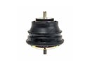 Ford Five Hundred Engine Mount
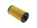 Ford Five Hundred Oil Filter
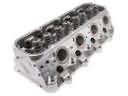 Ford Five Hundred Cylinder Head
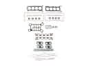 Ford Five Hundred Cylinder Head Gasket
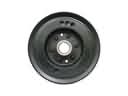 Ford Five Hundred Harmonic Balancer
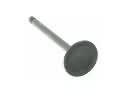 Ford Five Hundred Intake Valve
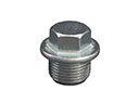 Ford Five Hundred Oil Drain Plug
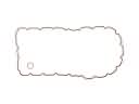 Ford Five Hundred Oil Pan Gasket
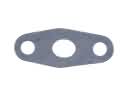 Ford Five Hundred Oil Pump Gasket
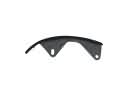 Ford Five Hundred Timing Chain Guide
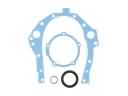 Ford Five Hundred Timing Cover Gasket
 Ford Five Hundred Valve Stem Seal