FordParts
My Garage
My Account
Cart
OEM Ford Freestar Brake Pedal
Brake Pedal Pad- Select Vehicle by Model
- Select Vehicle by VIN
Select Vehicle by Model
orMake
Model
Year
Select Vehicle by VIN
For the most accurate results, select vehicle by your VIN (Vehicle Identification Number).
2 Brake Pedals found

Ford Freestar Pedal Assembly Part Number: 3F2Z-2455-BA
Ford Freestar Pedal Assembly Part Number: 3F2Z-2455-AA
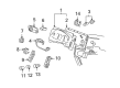
Ford Freestar Brake Pedal
OEM Brake Pedal boasts unmatched quality. Each part goes through full quality checks. They adhere to Ford's official factory standards. These steps remove flaws and inconsistencies. So you can get Brake Pedal with long life and a perfect fit. Come to our website and find genuine Ford Freestar parts. We keep a wide inventory of OEM Freestar parts at the highly affordable prices. It's easy to search, compare, and pick what you need. You'll love the clear info and simple checkout. We offer top-rated customer service, and we reply fast. We also ship promptly to ensure your order arrives on time.
Ford Freestar Brake Pedal Parts and Q&A
- Q: How to service and repair the brake pedal assembly on Ford Freestar?A:Before servicing or repairing the brake pedal assembly start by moving adjustable pedals to the maximum forward extent. The steering column opening cover requires tightening to 8 Nm (71 inch lbs.) on its three bolts before removing the cover itself. The following installation step requires removal of two steering column opening reinforcement bolts followed by its removal while tightening to 8 Nm (71 inch lbs.). The first step is to disconnect the left-hand side demister duct after which technicians need to remove and securely set aside the steering intermediate shaft by tightening its upper bolt to 30 Nm (22 ft. lbs.). Separate the extra self-locking clips from both the cover and the clip itself. Remove the brake pedal position (BPP) switch together with booster rod along with bushing from the brake pedal. Lessen pressure on the Accelerator Cable from the accelerator pedal arm and the plastic plunger when steering vehicles with adjustable pedals. The adjustable pedal motor electrical connector must be disconnected at the top of the bracket when the vehicle has this feature enabled. First remove four brake booster nuts and tighten them to 25 Nm (18 ft. lbs.) reinstall them before unfastening the two upper brake pedal bracket bolts that need tightening to 25 Nm (18 ft. lbs.) as well. The brake pedal assembly along with bracket must be removed before you can finish the installation by doing the opposite of removal steps.

Related Ford Freestar Parts
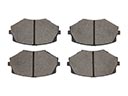 Ford Freestar Brake Pads
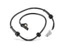 Ford Freestar ABS Sensor
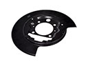 Ford Freestar Backing Plate
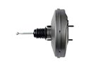 Ford Freestar Brake Booster
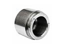 Ford Freestar Brake Caliper Piston
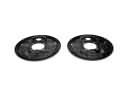 Ford Freestar Brake Dust Shields
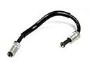 Ford Freestar Brake Line
 Ford Freestar Brake Master Cylinder
 Ford Freestar Brake Rotor
 Ford Freestar Hydraulic Hose
 Ford Freestar Parking Brake Cable
 Ford Freestar Wheel Hub