FordParts
My Garage
My Account
Cart
OEM Lincoln MKS Vehicle Speed Sensor
VSS- Select Vehicle by Model
- Select Vehicle by VIN
Select Vehicle by Model
orMake
Model
Year
Select Vehicle by VIN
For the most accurate results, select vehicle by your VIN (Vehicle Identification Number).
4 Vehicle Speed Sensors found


Lincoln MKS Speed Sensor Part Number: DG1Z-9E731-G
$1061.85 MSRP: $1763.15You Save: $701.30 (40%)Ships in 1 Business Day
Lincoln MKS Speed Sensor Part Number: 4R8Z-9E731-A
$1372.25 MSRP: $1898.38You Save: $526.13 (28%)Ships in 1-2 Business Days


Lincoln MKS Speed Sensor Part Number: DG1Z-9E731-B
Lincoln MKS Speed Sensor Part Number: AE9Z-9E731-C
Lincoln MKS Vehicle Speed Sensor
OEM Vehicle Speed Sensor boasts unmatched quality. Each part goes through full quality checks. They adhere to Lincoln's official factory standards. These steps remove flaws and inconsistencies. So you can get Vehicle Speed Sensor with long life and a perfect fit. Come to our website and find genuine Lincoln MKS parts. We keep a wide inventory of OEM MKS parts at the highly affordable prices. It's easy to search, compare, and pick what you need. You'll love the clear info and simple checkout. We offer top-rated customer service, and we reply fast. We also ship promptly to ensure your order arrives on time.
The Lincoln MKS Vehicle Speed Sensor is a critical part that helps to call attention to the dependability and power of Lincoln MKS, a full-size luxury car manufactured from 2008 to 2016. This Vehicle Speed Sensor is specifically vital to manage the vehicle dynamics by measuring and calculating the velocity of the car and by monitoring the rate of revolution of all the wheels. Through the provision of requisite data to the vehicle computer systems the Lincoln MKS Vehicle Speed Sensor contributes to efficiency of systems such as the engine and the anti-lock braking system (ABS) hence enhancing safety while on road. The originally applied Mechanical Linkage Type has been replaced by complex systems to perform further functions that are now characteristic of the Lincoln MKS Vehicle Speed Sensor and set it apart in the market. This Vehicle Speed Sensor can be used on numerous MKS models and is usually comprised of a ferromagnetic toothed ring together with passive or even active sensor pieces, so that the output can be as accurate as is necessary for the vehicle. Lincoln MKS is exquisite and elegant car with exquisite look, marked by the famous waterfall grille, and improved safety features, and supported by the efficiency of the Vehicle Speed Sensor. In light of this, the Lincoln MKS Vehicle Speed Sensor move with the ever-changing driving conditions to ensure safe and comfortable driving while, at the same time, acting as an added plus to the Lincoln brand, viewing itself as a company focusing not only on quality but also innovation. In total, the Lincoln MKS Vehicle Speed Sensor is a crucial part which adds to the vehicle performance and it also assists the company in maintaining the high repute of its cars.
Lincoln MKS Vehicle Speed Sensor Parts and Q&A
- Q: How to Service and Repair a Vehicle Speed Sensor on a 6F50 Transmission on Lincoln MKS?A:Start the service and repair process of the Output Shaft Speed (OSS) sensor for a 6F50 transmission when you place your vehicle on a hoist while keeping it in neutral position. The vehicle requires disconnecting two components: the Mass Air Flow (MAF) sensor electrical connector and the engine breather from the Air Cleaner (ACL) assembly. Begin by unscrewing both ACL assembly bracket bolts while loosening the outlet pipe clamp at the Throttle Body and afterward remove the ACL and outlet pipe assembly. You should drain transmission fluid with the drain plug and reinstall it by tightening it to a torque of 9 Nm (80 lb-in). First remove the selector lever cable from its connection point with the manual control lever and next move away the coolant hoses from the transmission fluid filler tube. Tear off the transmission fluid level indicator before removing the nut which allows you to detach the transmission fluid filler tube by rotating it counterclockwise 90 degrees. Cresent the thermal bypass valve connector on the transmission fluid cooler tube, discard the bolt from the hose and detach the tube. Verify that the transmission fluid cooler tube seal along with its backing ring do not remain stuck inside the transaxle case. Remove the obstructions if they are present. First disconnect the transaxle electrical connector before removing the fastener which secures the wiring harness to the main control cover stud. You should start by removing the nut and manual control lever before taking out the two nuts which will allow you to pull the thermal bypass valve upward. First remove the 14 bolts from the main control cover while making a mental note of where the stud bolts should be placed for subsequent reinstallation. The user must disconnect the Transmission Range (TR) sensor electrical connector followed by detaching the Turbine Shaft Speed (TSS) and OSS sensor electrical connectors. Handle the solenoid body carefully when removing its eleven bolts because the leadframe area and solenoid body filter screens should be avoided to prevent damage during removal. Detach the solenoid body filter assembly in an upward direction and discard the filter component. Disassemble the 10 bolts and TR sensor detent spring and main control valve body where you should later install the bolt and OSS sensor. The first installation step requires you to fit the OSS sensor along with its bolt which needs to be tightened to 12 Nm (106 lb-in). Before placing the main control valve body always make sure to correctly install the manual pin from the TR sensor within the manual valve. Screw in the ten bolts and TR sensor detent spring in the proper order while tightening them to 12 Nm (106 lb-in). The new solenoid body filter assembly needs correct alignment before its installation with 11 bolts of different lengths until it reaches 12 Nm (106 lb-in) torque. Connect the electrical connectors of OSS, TR and TSS sensors while making sure the wiring harnesses avoid any pinching. Check the transaxle side cover seal for damage then conduct replacement when needed. Attach the main control cover after positioning the solenoid body connector seal in the correct spot and tighten the 14 bolts to a torque of 12 Nm (106 lb-in). Fasten the thermal bypass valve together with the cooler tube assembly while tightening its connecting nuts to 9 Nm (80 lb-in). Install the wiring harness fastener while connecting both the transaxle electrical connector to its components. Subject the transmission fluid cooler tube seal to inspection then lubrication before installing it with a new bolt tightened to 9 Nm (80 lb-in) along with the cooler tube fitting tightened to 25 Nm (18 lb-ft). After installation of the manual control lever along with its tightening nut to 18 Nm (159 lb-in) the service technician must tighten the transmission fluid filler tube with its nut to 11 Nm (97 lb-in). The technician then performs the installation of the transmission fluid level indicator. Guide the coolant hoses to their original placement which should be at the transmission fluid filler tube location. After placing the manual control lever into drive position separate the selector lever cable end from the manual control lever before fixing the adjuster in place. The ACL assembly requires installation with 11 Nm (97 lb-in) of torque on the two bracket bolts while the ACL outlet pipe clamp at the TB needs 5 Nm (44 lb-in) of torque for the installation and reconnecting the engine breather to the ACL assembly and MAF sensor electrical connector reattachment. The transmission space requires clean fluid at its proper measurement.

Related Lincoln MKS Parts
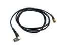 Lincoln MKS Antenna Cable
 Lincoln MKS Body Control Module
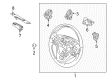
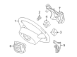
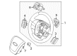
 Lincoln MKS Clock Spring
 Lincoln MKS Dome Light
 Lincoln MKS Ignition Lock Cylinder
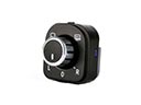 Lincoln MKS Mirror Switch
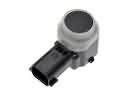 Lincoln MKS Parking Assist Distance Sensor
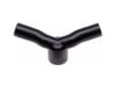 Lincoln MKS PCV Hose
 Lincoln MKS Seat Cover
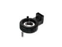 Lincoln MKS Steering Angle Sensor
 Lincoln MKS Wiper Blade
 Lincoln MKS Wiper Motor