FordParts
My Garage
My Account
Cart
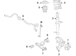
OEM Mercury Sable Coil Springs
Strut Spring- Select Vehicle by Model
- Select Vehicle by VIN
Select Vehicle by Model
orMake
Model
Year
Select Vehicle by VIN
For the most accurate results, select vehicle by your VIN (Vehicle Identification Number).
24 Coil Springs found


Mercury Sable Coil Spring, Rear Part Number: 8G1Z-5560-C
$94.74 MSRP: $131.06You Save: $36.32 (28%)Ships in 1-2 Business Days
Mercury Sable Spring, Rear Part Number: 5F1Z-5560-D
$6.10 MSRP: $8.44You Save: $2.34 (28%)Ships in 1-2 Business Days
Mercury Sable Coil Spring, Front Part Number: E6DZ5310D
$7.25 MSRP: $10.04You Save: $2.79 (28%)Ships in 1-2 Business Days
Mercury Sable Coil Spring, Front Part Number: F6DZ-5310-A
$11.63 MSRP: $16.09You Save: $4.46 (28%)Ships in 1-2 Business DaysMercury Sable Coil Spring, Front Part Number: 4F1Z-5310-AA
$17.09 MSRP: $23.64You Save: $6.55 (28%)Ships in 1-2 Business Days
Mercury Sable Coil Spring, Front Part Number: 8G1Z-5310-F
$32.91 MSRP: $45.53You Save: $12.62 (28%)Ships in 1-2 Business Days
Mercury Sable Coil Spring, Front Part Number: 8G1Z-5310-A
$42.40 MSRP: $58.66You Save: $16.26 (28%)Ships in 1-2 Business Days


Mercury Sable Coil Spring, Rear Part Number: 8G1Z-5560-D


Mercury Sable Coil Spring, Rear Part Number: 2F1Z-5560-BB
Mercury Sable Coil Spring, Front Part Number: 4F1Z-5310-BA
Mercury Sable Coil Spring, Rear Part Number: F6DZ-5560-X
Mercury Sable Coil Spring, Rear Part Number: F6DZ-5560-S

Mercury Sable Coil Spring, Rear Part Number: F6DZ-5560-M

Mercury Sable Spring, Front Part Number: F6DZ-5310-F
Mercury Sable Coil Spring Part Number: E6DZ5310T
Mercury Sable Spring, Front Part Number: E6DZ5310AG
Mercury Sable Coil Spring, Front Part Number: 8G1Z-5310-E
Mercury Sable Coil Spring, Front Part Number: 8G1Z-5310-B
Mercury Sable Coil Spring, Rear Part Number: 6F1Z-5560-A

Mercury Sable Spring, Rear Part Number: 4F1Z-5560-AA
| Page 1 of 2 |Next >
1-20 of 24 Results
Mercury Sable Coil Springs
OEM Coil Springs boasts unmatched quality. Each part goes through full quality checks. They adhere to Mercury's official factory standards. These steps remove flaws and inconsistencies. So you can get Coil Springs with long life and a perfect fit. Come to our website and find genuine Mercury Sable parts. We keep a wide inventory of OEM Sable parts at the highly affordable prices. It's easy to search, compare, and pick what you need. You'll love the clear info and simple checkout. We offer top-rated customer service, and we reply fast. We also ship promptly to ensure your order arrives on time.
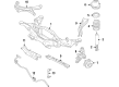
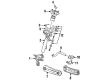
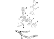
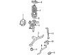
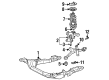
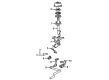
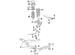
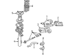
The Mercury Sable coil springs are vital parts of the car which has a reputation for its great suspensions. Intended for bearing the weight of Mercury Sable and for leveling the shocks received from irregularities of the roads these coil springs are rather important elements of precise wheel positioning. This functionality eradicates cases of sags, uneven wear on tires, and a situation where a car descends too low to the ground as it will maintain a good ride height. Compatible with different generations of the Sable cars that include the five generations, the Mercury coil springs come in linear rate, progressive and dual rate types that improve the handling and ride comfort of the car. variable rate or cargo coils available for higher frequency carriers add to the efficiency and safety of Sable. Also, the coilovers are adjustable and so are many of the springs to adjust the height and like such matters as different wheel and tires from vehicle can be well catered for. Mercury Sable, a mid-size sedan car that grown into fame because of its advanced look and its impressive performance, Mercury Sable is specially known for its stability and comfortable feeling and its coil springs can be considered very forefront in the market. The coil springs not only offer improved performance but also increase safety and thus the Mercury Sable is a perfect example of the brand's reliability and the car's all rounded characteristics making the Sable the premier car for drivers who are in need of a reliable car to use.
Mercury Sable Coil Springs Parts and Q&A
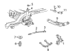
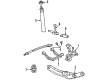
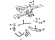
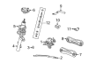
- Q: How to Service and Repair Coil Springs on a Spring-Wagon on Mercury Sable?A:The first step to servicing or repairing the Spring-Wagon coil spring demands a technician to use level-ground conditions for measuring distance from wheel hub center to fender lip while removing wheel covers. Begin by untightening the bolt which enables removal of the rear brake hose union bracket. Then perform the step of removing the rear wheel and tire assembly. Attach a jack stand to support the rear suspension arm and bushing before you discard the bolts and flag nuts used to keep the stabilizer bar bracket intact. Supporting the lower Control Arm with a proper method must happen prior to removing either the upper or lower Shock Absorber fasteners because this prevents attached parts from getting damaged. The shock absorber becomes free after discarding both the bolt and nut to separate it from the system along with discarding the washer and bushing. Discard the nuts and four washers and flag bolts after which you can separate the tension strut from the rear wheel Spindle. After lowering the lower control arm with the jack stand it becomes possible to remove the rear spring along with the rear spring center mounting insulator as one unit but you must discharge the rear spring center mounting insulator and rear spring insulator in sequence. Start your installation process with the rear spring insulator and verify correct seating position before installing the rear spring center mounting insulator similarly. Mount the rear spring together with the rear spring center mounting insulator while making sure the rear spring fits properly into the lower control arm position. Guiding the rear spring center mounting insulator into the underbody spring seat requires you to use the jack stand when raising the rear suspension arm and bushing incrementally. Through the use of a jack stand place the tension strut into the rear wheel spindle before finally setting the lower control arm. The technician should add four retaining washers and new nuts to the Rag bolts before leaving them untightened. Position the bushing with its washer and new nut after facing the washer cup towards the outer side. Place the shock absorber and then install a fresh bolt. The suspension should be raised until it reaches the target curb height measurement from the fender lip to the hub center. The nuts must be fully tightened at this moment. The stabilizer bar bracket receives installation with both the nut and retainer assembly while new bolts and new Rag nuts get attached. Maintaining control by eliminatig the jack stand you can partially lower the vehicle to put in both the rear brake hose union bracket along with its bolt. Put the wheel on and attach the tire before examining wheel alignment while performing required corrections.

Related Mercury Sable Parts
 Mercury Sable Axle Beam
 Mercury Sable Camber and Alignment Kit
 Mercury Sable Control Arm Bolt
 Mercury Sable Control Arm Bushing
 Mercury Sable Lateral Link
 Mercury Sable Shock and Strut Boot
 Mercury Sable Suspension Strut Rod
 Mercury Sable Sway Bar Bushing
 Mercury Sable Sway Bar Link
 Mercury Sable Sway Bars
 Mercury Sable Torsion Bar
 Mercury Sable Trailing Arm Bushing