My Garage
Cart
Make sure this part fits

Ford 7E5Z-5484-A
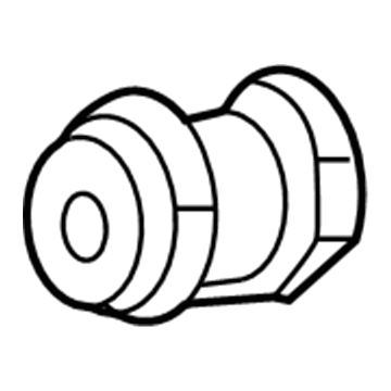
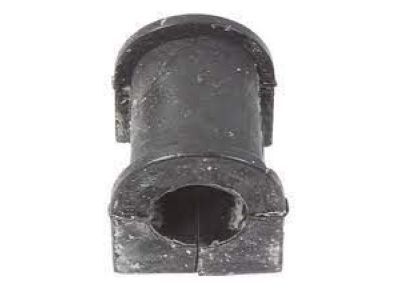
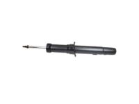
Stabilizer Bar Bushing, Front

2006-2009 Ford 7E5Z5484A

Customer Questions & Expert Answers (4)
Ford 7E5Z-5484-A Stabilizer Bar Bushing, Front
  • Part Description
    Bush; Front Suspension Stabilizer Bar Bushing Kit.
  • Base No.
    5484
  • Position
    Front
  • Manufacturer
    Ford
Make sure this part fits
$9.31 MSRP: $13.20
You Save: $3.89 (30%)
Ships in 1-3 Business Days
1
ADD TO CART
  • Related Parts
  • Product Specifications
  • Vehicle Fitment
  • Customer Questions & Expert Answers
  • Product Specifications

    BrandGenuine Ford
    Base No.5484
    Manufacturer Part Number7E5Z-5484-A
    Part DescriptionBush; Front Suspension Stabilizer Bar Bushing Kit.
    Other NamesBushings
    Item Weight0.30 Pounds
    PositionFront
    ConditionNew
    Fitment TypeDirect Replacement
    Require Quantity2
    ManufacturerFord
    SKU7E5Z-5484-A
    WarrantyThis genuine Ford part is guaranteed by Ford's factory warranty.
    Shipping & ReturnShipping Policy Return Policy
    Warning: California's Proposition 65
  • Vehicle Fitment

    Year Make Model Trim Engine
    2006-2009 Ford FusionS, SE, SEL4 Cyl 2.3 L GAS, 6 Cyl 3.0 L GAS
    2007-2009 Lincoln MKZBase6 Cyl 3.5 L GAS
    2006 Lincoln ZephyrBase6 Cyl 3.0 L GAS
    2006-2009 Mercury MilanBase, Premier4 Cyl 2.3 L GAS, 6 Cyl 3.0 L GAS
  • Customer Questions & Expert Answers

    Q:
    Can you verify if 7E5Z-5484-A is the right one for my car? Posted by FordPartsDeal Specialist
    A:
    Select Your Vehicle model to verify if part number 7E5Z-5484-A fits your car.
    Posted by FordPartsDeal Specialist
    Q:
    How to Service and Repair the Front Sway Bar Bushing in the Suspension on Ford Fusion? Posted by Customer
    A:
    The first step for sway bar bushing front suspension maintenance requires users to set the steering wheel at straight-ahead and turn the ignition OFF. Detach the steering column shaft joint cover bolts at the bottom and pull out the cover assembly. The safety of the Clock Spring depends on a static steering column shaft because any shaft rotation during disconnection could damage the component. Such damage requires complete removal and centering of the Clock Spring. Establish an index on the steering column shaft for assembly reference before detaching it from the steering gear using the bolt while maintaining alignment of the marks during reinstall and pulling the bolt to 25 Nm torque (18 lb-ft). The steering column shaft-to-dash seal needs removal before installing the seal onto the steering gear correctly while ensuring all retaining clips are secured to avoid seal damage. To proceed, place the vehicle in NEUTRAL position on a hoist system before unscrewing eight mounting screws that allow you to set aside the LH and RH splash shields. Uninstall both splash shields by removing their six pin-type retainers, yet maintain 7 Nm (62 lb-in) torque when reinstalling the parts. Additionally, if an underbody cover shield is present, remove its bolts doing the same torque installation before reinstalling. Discard the old tie-rod end cotter pins and nuts and use fresh parts which should be torqued to 48 Nm (35 lb-ft) before installing newly placed cotter pins. A Tie-Rod End Remover tool should be used to detach both wheel knuckle tie-rod ends with no hammer application, which would protect the components from damage. Discard the two catalytic converter-to-exhaust flexible pipe nuts and divide the exhaust flexible pipe before tightening new nuts to 40 Nm (30 lb-ft) torque setting. All-wheel drive vehicles require driveshaft-to-Power Transfer Unit (PTU) indexing before bolt removal of the four units to set aside the driveshaft for reinstallation at 70 Nm (52 lb-ft). Begin by removing the RH steering gear-to-subframe bolt while making it 107 Nm (79 lb-ft) tight at reinstallation time. Then proceed to remove the two LH steering gear-to-subframe bolts before positioning the steering gear to reach the sway bar LH bracket front nut. Re-torque to 107 Nm (79 lb-ft) when reinstalling. Discard the four sway bar bracket nuts before uninstalling both sway bar brackets. Reinstall the new bracket nuts at 48 Nm (35 lb-ft). Before torquing sway bar bracket nuts, use a suitable jack to raise the suspension until the hub center sits 402 mm (15.83 in) from the fender lip. This will prevent clamp load-induced bushing damage. Perform the reverse of this removal method during installation.
    Posted by FordPartsDeal Specialist
    Q:
    How to Service and Repair the Front Sway Bar Bushing in the Suspension on Lincoln MKZ? Posted by Customer
    A:
    The first step for sway bar bushing front suspension maintenance requires users to set the steering wheel at straight-ahead and turn the ignition OFF. Detach the steering column shaft joint cover bolts at the bottom and pull out the cover assembly. The safety of the Clock Spring depends on a static steering column shaft because any shaft rotation during disconnection could damage the component. Such damage requires complete removal and centering of the Clock Spring. Establish an index on the steering column shaft for assembly reference before detaching it from the steering gear using the bolt while maintaining alignment of the marks during reinstall and pulling the bolt to 25 Nm torque (18 lb-ft). The steering column shaft-to-dash seal needs removal before installing the seal onto the steering gear correctly while ensuring all retaining clips are secured to avoid seal damage. To proceed, place the vehicle in NEUTRAL position on a hoist system before unscrewing eight mounting screws that allow you to set aside the LH and RH splash shields. Uninstall both splash shields by removing their six pin-type retainers, yet maintain 7 Nm (62 lb-in) torque when reinstalling the parts. Additionally, if an underbody cover shield is present, remove its bolts doing the same torque installation before reinstalling. Discard the old tie-rod end cotter pins and nuts and use fresh parts which should be torqued to 48 Nm (35 lb-ft) before installing newly placed cotter pins. A Tie-Rod End Remover tool should be used to detach both wheel knuckle tie-rod ends with no hammer application, which would protect the components from damage. Discard the two catalytic converter-to-exhaust flexible pipe nuts and divide the exhaust flexible pipe before tightening new nuts to 40 Nm (30 lb-ft) torque setting. All-wheel drive vehicles require driveshaft-to-Power Transfer Unit (PTU) indexing before bolt removal of the four units to set aside the driveshaft for reinstallation at 70 Nm (52 lb-ft). Begin by removing the RH steering gear-to-subframe bolt while making it 107 Nm (79 lb-ft) tight at reinstallation time. Then proceed to remove the two LH steering gear-to-subframe bolts before positioning the steering gear to reach the sway bar LH bracket front nut. Re-torque to 107 Nm (79 lb-ft) when reinstalling. Discard the four sway bar bracket nuts before uninstalling both sway bar brackets. Reinstall the new bracket nuts at 48 Nm (35 lb-ft). Before torquing sway bar bracket nuts, use a suitable jack to raise the suspension until the hub center sits 402 mm (15.83 in) from the fender lip. This will prevent clamp load-induced bushing damage. Perform the reverse of this removal method during installation.
    Posted by FordPartsDeal Specialist
    Q:
    How to Service and Repair the Front Sway Bar Bushing in the Suspension on Mercury Milan? Posted by Customer
    A:
    The first step for sway bar bushing front suspension maintenance requires users to set the steering wheel at straight-ahead and turn the ignition OFF. Detach the steering column shaft joint cover bolts at the bottom and pull out the cover assembly. The safety of the Clock Spring depends on a static steering column shaft because any shaft rotation during disconnection could damage the component. Such damage requires complete removal and centering of the Clock Spring. Establish an index on the steering column shaft for assembly reference before detaching it from the steering gear using the bolt while maintaining alignment of the marks during reinstall and pulling the bolt to 25 Nm torque (18 lb-ft). The steering column shaft-to-dash seal needs removal before installing the seal onto the steering gear correctly while ensuring all retaining clips are secured to avoid seal damage. To proceed, place the vehicle in NEUTRAL position on a hoist system before unscrewing eight mounting screws that allow you to set aside the LH and RH splash shields. Uninstall both splash shields by removing their six pin-type retainers, yet maintain 7 Nm (62 lb-in) torque when reinstalling the parts. Additionally, if an underbody cover shield is present, remove its bolts doing the same torque installation before reinstalling. Discard the old tie-rod end cotter pins and nuts and use fresh parts which should be torqued to 48 Nm (35 lb-ft) before installing newly placed cotter pins. A Tie-Rod End Remover tool should be used to detach both wheel knuckle tie-rod ends with no hammer application, which would protect the components from damage. Discard the two catalytic converter-to-exhaust flexible pipe nuts and divide the exhaust flexible pipe before tightening new nuts to 40 Nm (30 lb-ft) torque setting. All-wheel drive vehicles require driveshaft-to-Power Transfer Unit (PTU) indexing before bolt removal of the four units to set aside the driveshaft for reinstallation at 70 Nm (52 lb-ft). Begin by removing the RH steering gear-to-subframe bolt while making it 107 Nm (79 lb-ft) tight at reinstallation time. Then proceed to remove the two LH steering gear-to-subframe bolts before positioning the steering gear to reach the sway bar LH bracket front nut. Re-torque to 107 Nm (79 lb-ft) when reinstalling. Discard the four sway bar bracket nuts before uninstalling both sway bar brackets. Reinstall the new bracket nuts at 48 Nm (35 lb-ft). Before torquing sway bar bracket nuts, use a suitable jack to raise the suspension until the hub center sits 402 mm (15.83 in) from the fender lip. This will prevent clamp load-induced bushing damage. Perform the reverse of this removal method during installation.
    Posted by FordPartsDeal Specialist
    If you have any questions about this product, please don't hesitate to ask us. We will be happy to help you!

OEM Ford 7E5Z-5484-A, Excellent Performance and Perfect Fitment

To ensure reliability, purchase Ford part # 7E5Z-5484-A Stabilizer Bar Bushing, Front. It is sometimes referred to as Ford Sway Bar Bushing. For those Ford owners who aspire to maintain their vehicles in optimal shape, opting for OEM parts is a wise choice. Precisely engineered, these components adhere to stringent factory guidelines and are produced in state-of-the-art facilities using cutting-edge technologies. Moreover, they are subjected to thorough testing to certify their resilience and safety, thereby making them a dependable option for Ford owners.

FordPartsDeal.com is a leading supplier of genuine Ford parts such as Ford 7E5Z5484A Stabilizer Bar Bushing, Front. A vast selection of genuine Ford parts is available on our website, all offered at discounted prices. Every OEM Ford part is covered by the manufacturer's warranty, which also applies to our hassle-free return policy. Enjoy fast delivery service, ensuring you get your parts when you need them. Your shopping experience here is guaranteed to be pleasurable. For detailed Ford parts information, click here.
Choose FordPartsDeal for discounted prices, exceptional service and fast delivery