
Popular OEM Mercury Milan Parts
- Body & Hardware Parts View More >
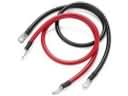
- Electrical Parts View More >
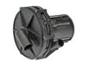
- Air & Fuel Delivery Parts View More >
- Steering Parts View More >
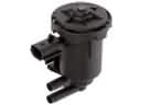
- Emission Control & Exhaust Parts View More >
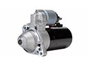
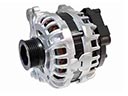
- Charging & Starting Parts View More >
- Engine Parts View More >
- Belts & Cooling Parts View More >
- Suspension Parts View More >
- Brakes Parts View More >
- A/C & Heating Parts View More >
- Headlights & Lighting Parts View More >


Why Buy Genuine Mercury Milan Parts From FordPartsDeal.com
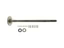
FordPartsDeal.com offers a smart and convenient way to buy genuine parts online. We sell new OEM Mercury Milan parts, including Transmission. Authorized dealers directly provide all the Mercury Milan parts and assemblies to ensure the optimal quality and fit. We also provide all properly fitting Mercury Milan parts, such as Driveline & Axles specific to your model. When you shop here, you get real Mercury value at highly competitive prices. All our products come with the same Mercury warranty available at other dealerships. Our easy-to-use catalog helps you quickly identify the right part for your car. You'll receive fast shipping from our warehouse network, keeping your Mercury Milan running smoothly. Our staff consists of Mercury professionals who are ready to assist you. We aim to treat each customer as if they were stepping out of a Mercury showroom. VIN verification and our live support ensure that the part you order is the right Mercury Milan part for your vehicle.
At the 2005 Chicago Auto Show, Mercury introduced the Milan mid-size sedan to the market as a Ford Motor Company subsidiary which sold until late 2010. Customers can choose between front-wheel drive and all-wheel drive systems in the Mercury Milan model which utilizes the CD3 platform according to its front-engine setup. The 2006 Mercury Milan has a 107.4-inch wheelbase, with a total length of 191.4 inches, a width of 72.2 inches, and a height of 55.8 inches. From its initial manufacturing time to 2010 the powertrain system of Mercury Milan received two upswings through different engine types: the first engine variant held a 2.3L I4 generating 160 hp followed by a 2.5L I4 engine making 175 hp in 2010. The 2010 model of the vehicle included a 3.0L V6 engine with flex-fuel functionality. The automatic transmission choices for the vehicle consisted of either a five-speed or a six-speed automatic which improved both driving capabilities and performance. The Mercury Milan manages handling and ride quality well because of its sturdy construction and genuine parts which received regular quality improvements across its manufacture. Contractors who want to extend the lifespan of their Mercury Milan vehicles should acquire authentic Mercury Milan components due to their original manufacturer standards which guarantee both durability and operational performance.
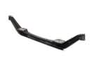
Mercury Milan has these problems categorized under powertrain control, suspension noise and shifter linkage operation. In tranny system the Milan can stumble, slip, slur or slam through the shifts. Software in the transmission control module and PCM may cause mismanagement issues, pressure, and time. Update each Milan module and assess fluid condition/adaptive data. Heavy wear may require valve body service if the updates don't help the Milan respond. For the suspension, the Milan can flex over bumps or while cornering. Movement and alignment drift are produced as a result of cracks or loose welds at the lower control arm. Install the revised lower control arm, lube strut interfaces, and check torques on all. On the shifter and console, the Milan may stick or refuse to move. A seizing shifter knob or binding bezel captures the release pawl and stops park interlock disengagement. Replace shifter knob or bezel, verify PRNDL alignment and road test the Mercury Milan. Mercury service instructions for calibrations, Mercury torque values during reassembly. Verify shift feel, temps and line pressure during a controlled road test. Document facts and re-submit adaptive tables if there is any repair to transmission.
Mercury Milan Parts and Q&A
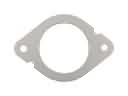
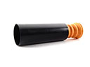
- Q: How to service the catalytic converter on Mercury Milan?A:In order to service the catalytic converter the vehicle should be hoisted in neutral. Take out the two nuts and gasket, tighten new to 40 Nm (30 ft. lbs. ) during re-installation. Take out the Torca clamp to disconnect the converter. Installation Reverse the installation procedure but use a new gasket and nuts. Check for exhaust leaks.
- Q: How to service the Water Pump on a 2.3L engine on Mercury Milan?A:In order to service the coolant pump of a 2.3L engine, lift the car, empty the cooling system, and loosen the pulley bolts. Take off pump and O-ring seal. Install the new pump, including lubricated O-ring, tighten bolts to 10 Nm and refill the cooling system.
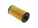
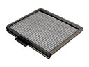
- Q: How to service and repair the air filter element on Mercury Milan?A:To change and clean the air filter element, begin by checking the parts of the intake air system, as indicated in the exploded view. Follow the steps of proper maintenance and replacement of the air filter element to ensure that the vehicle air intake system is operating at its best.


