FordParts
My Garage
My Account
Cart
OEM 2002 Ford Thunderbird Intake Manifold
Engine Intake Manifold- Select Vehicle by Model
- Select Vehicle by VIN
Select Vehicle by Model
orMake
Model
Year
Select Vehicle by VIN
For the most accurate results, select vehicle by your VIN (Vehicle Identification Number).
1 Intake Manifold found


2002 Ford Thunderbird Intake Manifold Part Number: XW4Z-9424-AH
Product Specifications- Other Name: Manifold Assembly - Inlet
- Base No.: 9424A
- Item Weight: 12.80 Pounds
- Item Dimensions: 9.4 x 20.8 x 16.5 inches
- Condition: New
- Fitment Type: Direct Replacement
- SKU: XW4Z-9424-AH
- Warranty: This genuine part is guaranteed by Ford's factory warranty.
2002 Ford Thunderbird Intake Manifold
If you're seeking quality and affordability, look no further than our extensive inventory of genuine 2002 Ford Thunderbird Intake Manifold available at FordPartsDeal.com. You can confidently purchase our OEM 2002 Ford Thunderbird Intake Manifold as they are supported by the manufacturer's warranty and our hassle-free return policy, alongside the benefit of our fast delivery service.
2002 Ford Thunderbird Intake Manifold Parts Q&A
- Q: How to service and repair the intake manifold on 2002 Ford Thunderbird?A: Service and repair of the intake manifold requires disconnecting the battery ground cable together with removing the air cleaner outlet tube. Engine damage will occur if you drain the cooling system equipment properly. The service requires removal of cowl vent screen and engine compartment brace together with disconnecting accelerator and speed control cables and vacuum hoses. Detach the exhaust manifold from the EGR valve tube then take out the two bolts to remove the EGR valve with its gasket discarded. The electrical CMP sensor connector should get disconnected before being removed from the fuel injection supply manifold. Efficiently detach the evaporative emission canister purge valve hose by compressing its normal fittings and retracting it in a straight motion to prevent damage. Begin the procedure by disconnecting the vacuum connector together with the fuel pressure sensor electrical connector before removing the fuel line. Disconnect all electrical connectors from the bracket which includes Knock Sensor (KS) and Cylinder Head Temperature (CHT) sensor before removing the bracket nut. Tilt the engine wiring harness for LH fuel injector connector removal as well as to unplug the Idle Air Control (IAC) valve and Throttle Position (TP) sensor electrical connectors. Release both the crankcase ventilation tube from RH valve cover and the throttle body hoses and perform the hose unclipping procedure before detaching it from the clip. The engine wiring harness should be raised for proper disconnection of RH fuel injectors before eliminating the differential pressure feedback sensor through removal of electrical connector and bolts with attached hoses. Workers can easily extract the intake manifold by removing only its bolts and stud but they do not need to unfasten the throttle body adapter nor the throttle body. Begin by removing specified bolts before taking out the stud and subsequently extracting the intake manifold. A plastic scraping tool should cleanse the sealing surfaces to prevent scratches before you check and possibly replace the gaskets. The first step is to install the gaskets followed by correct positioning of the throttle body heater return hose before you install the intake manifold through the specified bolt-tightening sequence. The differential pressure feedback sensor installation should be completed by attaching electrical connectors and hoses to it. Attach the engine wiring harness before you reconnect the RH fuel injector electrical connectors. At the same time attach hoses to the throttle body before you clip the hose into place. Next, the technician must reconnect the crankcase ventilation tube together with the IAC valve, TPS electrical connectors, then lastly the LH fuel injector electrical connectors. Install the bracket together with its associated nuts and hose followed by the electrical connector connection on the LH KS and CHT sensors bracket. Connect the fuel hose together with the vacuum connector to the fuel pressure sensor then join the fuel pressure sensor electrical connector. The procedure includes reconnecting the evaporative emission canister purge valve hose which should be followed by CMP sensor electrical connector attachment and then attachment of the exhaust manifold to the EGR valve tube. The EGR valve requires new gasket materials for installation with its two bolts while you should perform tight tube connections to vacuum hoses. The acceleration and speed control wires need to be reattached followed by installation of the engine compartment brace, cowl vent screen and air cleaner outlet tube. Rejoin the ground wire of the battery while executing proper engine cooling system filling and bleeding techniques to avoid damage to the engine parts.
Related 2002 Ford Thunderbird Parts
 2002 Ford Thunderbird Air Duct
 2002 Ford Thunderbird Air Filter
 2002 Ford Thunderbird Air Filter Box
 2002 Ford Thunderbird Air Intake Coupling
 2002 Ford Thunderbird Fuel Injector
 2002 Ford Thunderbird Fuel Pressure Regulator
 2002 Ford Thunderbird Fuel Pressure Sensor
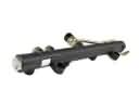 2002 Ford Thunderbird Fuel Rail
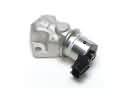 2002 Ford Thunderbird Idle Control Valve
 2002 Ford Thunderbird Intake Manifold Gasket
 2002 Ford Thunderbird Mass Air Flow Sensor
 2002 Ford Thunderbird Throttle Body