FordParts
My Garage
My Account
Cart
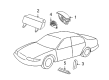
OEM 2005 Ford Focus Clock Spring
Spiral Cable Clock Spring- Select Vehicle by Model
- Select Vehicle by VIN
Select Vehicle by Model
orMake
Model
Year
Select Vehicle by VIN
For the most accurate results, select vehicle by your VIN (Vehicle Identification Number).
1 Clock Spring found


2005 Ford Focus Clockspring Part Number: 7S4Z-14A664-A
$141.47 MSRP: $218.32You Save: $76.85 (36%)Ships in 1-3 Business DaysProduct Specifications- Other Name: Cover And Contact Plate Assembly; Air Bag Clockspring
- Replaces: 4S4Z-14A664-AA
- Base No.: 14A664
- Item Weight: 0.90 Pounds
- Item Dimensions: 7.9 x 6.2 x 6.2 inches
- Condition: New
- Fitment Type: Direct Replacement
- SKU: 7S4Z-14A664-A
- Warranty: This genuine part is guaranteed by Ford's factory warranty.
2005 Ford Focus Clock Spring
If you're seeking quality and affordability, look no further than our extensive inventory of genuine 2005 Ford Focus Clock Spring available at FordPartsDeal.com. You can confidently purchase our OEM 2005 Ford Focus Clock Spring as they are supported by the manufacturer's warranty and our hassle-free return policy, alongside the benefit of our fast delivery service.
2005 Ford Focus Clock Spring Parts Q&A
- Q: What Precautions Should Be Taken When Servicing the Clock Spring Assembly to Minimize Injury Risk and Ensure Proper Functionality on 2005 Ford Focus?A: Put on safety glasses during repair sessions of the Clock Spring assembly because it helps protect from potential air bag deployments while also staying away from memory saver tools. The RCM fuse removal will turn the air bag warning lamp on during ignition ON situations but this condition does not signify an SRS fault. The SRS must operate without issues during the complete functionality test before you return the vehicle to the customer. When parts require replacement for repairs the diagnostic process should begin again after reinstallation of the original part. The repair process starts by depowering the system then requires you to remove the steering wheel along with disassembling the instrument panel lower knee bolster after removing its retaining screws and unclipping it. A thin-bladed screwdriver helps detach the steering column upper shroud from the lower shroud by releasing its clips on both sides. To detach the audio control switch from the lower shroud users must first release a locking tab followed by disconnecting its electrical connector. The lower shroud removal starts with operating the steering column locking lever before removing retaining screws. The same Clock Spring can be reused when users apply two strips of masking tape to the rotor of the Clock Spring to stop accidental movement. Begin by depressing the locking tabs to free each multifunction switch before lifting all switches up and disconnecting the Clock Spring electrical connector by using a thin-bladed tool to unlock its tab. After placing the spacing collar in the correct position within the Clock Spring center note the steering column locking tabs before unfastening them. Vehicles requiring Clock Spring recentering must have their road wheels in a straight position followed by turning the Clock Spring counterclockwise until sensation is met and then performing another clockwise rotation until the rotor's arrow points to the raised "V" section at the 12 o'clock position (requiring two and a half turns). The Clock Spring tape removal process should not entail spinning motions. Place the Clock Spring into position while making sure the column retaining tabs secure against the steering column followed by connecting the electrical connector and verifying an audible sound when the tabs correctly latch into place. After fitting the multifunction switches to the Clock Spring you can put the steering column lower shroud into place using the screws and lock the steering column locking mechanism. The audio control switch can be installed when present by inserting its electrical connector until it is securely attached. Secure the clip on the instrument panel lower knee bolster and install its screws before installing the steering column upper shroud. You should avoid rotating the new Clock Spring between breaking the red sealing key and installing the steering wheel because leaving the vehicle unattended requires a repeat of the centralizing procedure. Install the steering wheel with the right placement of the spacing collar but avoid its use when the collar is missing. The Clock Spring must be centralized before installing the steering wheel while electrician grease XG-12 must be applied generously to the driver air bag module electrical connector before connection to the Clock Spring for preventing SRS DTCs and connectivity problems. Finally, repower the SRS system.
Related 2005 Ford Focus Parts
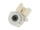 2005 Ford Focus Ignition Switch
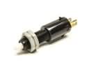 2005 Ford Focus Brake Light Switch
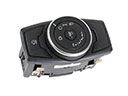 2005 Ford Focus Headlight Switch
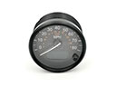 2005 Ford Focus Speedometer
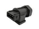 2005 Ford Focus Vehicle Speed Sensor
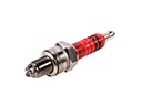 2005 Ford Focus Spark Plug
 2005 Ford Focus Air Bag
 2005 Ford Focus Air Bag Control Module
 2005 Ford Focus Air Bag Sensor
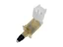 2005 Ford Focus Door Jamb Switch
 2005 Ford Focus MAP Sensor
 2005 Ford Focus Temperature Sender