FordParts
My Garage
My Account
Cart
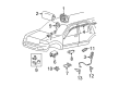
OEM 2006 Ford F-150 Clock Spring
Spiral Cable Clock Spring- Select Vehicle by Model
- Select Vehicle by VIN
Select Vehicle by Model
orMake
Model
Year
Select Vehicle by VIN
For the most accurate results, select vehicle by your VIN (Vehicle Identification Number).
1 Clock Spring found


2006 Ford F-150 Clockspring Part Number: 8L3Z-14A664-A
Product Specifications- Other Name: Cover And Contact Plate Assembly; Air Bag Clockspring
- Replaces: 2L2Z-14A664-AB, 7L3Z-14A664-A
- Base No.: 14A664
- Item Weight: 0.90 Pounds
- Item Dimensions: 8.2 x 6.1 x 4.5 inches
- Condition: New
- Fitment Type: Direct Replacement
- SKU: 8L3Z-14A664-A
- Warranty: This genuine part is guaranteed by Ford's factory warranty.
2006 Ford F-150 Clock Spring
Achieve unprecedented performance experience with our genuine 2006 Ford F-150 Clock Spring. All our parts are engineered for a perfect fit and maximum durability to ensure that your F-150 returns to factory condition. Specially designed for the 2006 Ford F-150, this Clock Spring offers superior reliability and ease of installation for anyone.
If you're seeking quality and affordability, look no further than our extensive inventory of genuine 2006 Ford F-150 Clock Spring available at FordPartsDeal.com. You can confidently purchase our OEM 2006 Ford F-150 Clock Spring as they are supported by the manufacturer's warranty and our hassle-free return policy, alongside the benefit of our fast delivery service.
Related 2006 Ford F-150 Parts
 2006 Ford F-150 Air Bag
 2006 Ford F-150 Air Bag Control Module
 2006 Ford F-150 Air Bag Sensor
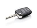 2006 Ford F-150 Car Key
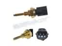 2006 Ford F-150 Cylinder Head Temperature Sensor
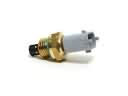 2006 Ford F-150 Intake Manifold Temperature Sensor
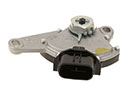 2006 Ford F-150 Neutral Safety Switch
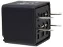 2006 Ford F-150 Relay
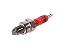 2006 Ford F-150 Spark Plug
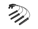 2006 Ford F-150 Spark Plug Wire
 2006 Ford F-150 Vehicle Speed Sensor
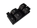 2006 Ford F-150 Window Switch