FordParts
My Garage
My Account
Cart
OEM 2009 Ford Expedition Timing Cover
Engine Timing Cover- Select Vehicle by Model
- Select Vehicle by VIN
Select Vehicle by Model
orMake
Model
Year
Select Vehicle by VIN
For the most accurate results, select vehicle by your VIN (Vehicle Identification Number).
1 Timing Cover found


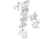
2009 Ford Expedition Timing Cover, Front Part Number: 7L3Z-6019-A
$139.69 MSRP: $203.33You Save: $63.64 (32%)Ships in 1-3 Business DaysProduct Specifications- Other Name: Cover - Cylinder Front; Engine Timing Cover; Front Cover
- Position: Front
- Replaces: 3L3Z-6019-GA
- Base No.: 6019
- Item Weight: 8.60 Pounds
- Item Dimensions: 26.0 x 23.9 x 5.2 inches
- Condition: New
- Fitment Type: Direct Replacement
- SKU: 7L3Z-6019-A
- Warranty: This genuine part is guaranteed by Ford's factory warranty.
2009 Ford Expedition Timing Cover
If you're seeking quality and affordability, look no further than our extensive inventory of genuine 2009 Ford Expedition Timing Cover available at FordPartsDeal.com. You can confidently purchase our OEM 2009 Ford Expedition Timing Cover as they are supported by the manufacturer's warranty and our hassle-free return policy, alongside the benefit of our fast delivery service.
2009 Ford Expedition Timing Cover Parts Q&A
- Q: How to service and repair the timing cover on 2009 Ford Expedition?A: In order to fix the timing cover, lift the vehicle and take out the valve covers, cooling fan and the accessory drive belt. Separate all the parts, such as crankshaft pulley and front oil seal. Install a new front cover gasket, screw in fasteners and re-connect sensors. Lastly, fit the cooling fan, valve covers and pour some oil into the crankcase.
Related 2009 Ford Expedition Parts
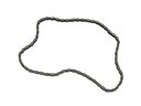 2009 Ford Expedition Timing Chain
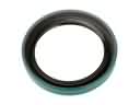 2009 Ford Expedition Crankshaft Seal
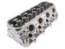 2009 Ford Expedition Cylinder Head
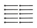 2009 Ford Expedition Cylinder Head Bolts
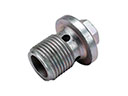 2009 Ford Expedition Drain Plug
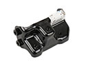 2009 Ford Expedition Engine Mount Bracket
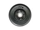 2009 Ford Expedition Harmonic Balancer
 2009 Ford Expedition Intake Valve
 2009 Ford Expedition Oil Pan
 2009 Ford Expedition Rocker Arm
 2009 Ford Expedition Rod Bearing
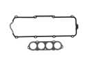 2009 Ford Expedition Valve Cover Gasket